Video Library (VL) calls let you perform video teleconferencing, blend computer-generated graphics with frames from videotape or any video source, and output the input video source to the graphics monitor, to a video device such as a VCR, or both.
This chapter explains the basics of creating video programs for OCTANE Digital Video:
Syntax elements are as follows:
VL types and constants begin with uppercase VL; for example, VLServer
VL functions begin with lowercase vl; for example, vlOpenVideo()
Data transfers fall into two categories:
transfers involving memory (video to memory, memory to video), which require setting up a buffer
transfers not involving memory (such as video to screen and graphics to video), which do not require a buffer
For the two categories of data transfer, based on the VL programming model, the process of creating a VL application consists of these steps:
Open a connection to the video daemon (vlOpenVideo()); if necessary, determine which device the application will use (vlGetDevice(), vlGetDeviceList()).
Specify nodes on the data path (vlGetNode()).
Create the path (vlCreatePath()).
(Optional step) Add more connections to a path (vlAddNode()).
Set up the hardware for the path (vlSetupPaths()).
Specify path-related events to be captured (vlSelectEvents()).
Set input and output parameters (controls) for the nodes on the path (vlSetControl()).
For transfers involving memory, create a VL buffer to hold data for memory transfers (vlGetTransferSize(), dmBufferCreatePool() or vlCreateBuffer()).
For transfers involving memory, register the buffer (vlRegisterBuffer()) or (video-to-memory only) vlDMBufferPoolRegister()
Set the path topology (vlSetConnection()).
Start the data transfer (vlBeginTransfer()).
For transfers involving memory, get the data and manipulate it (DMbuffers: vlDMBufferGetValid(), vlGetActiveRegion(), dmBufferFree(); VL buffers: vlGetNextValid(), vlGetLatestValid(), vlGetActiveRegion(), vlPutFree()).
Clean up (vlEndTransfer(), vlDeregisterBuffer(), vlDestroyPath(), dmBuffer() or vlDestroyBuffer(), vlCloseVideo()).
To build programs that run under VL, you must
install the dmedia_dev option
link with libvl.so
include vl.h and dev_mgv.h
The client library is /usr/lib/libvl.so. The header files for the VL are in /usr/include/dmedia. The header file for the VL, vl.h, contains the main definition of the VL API and controls. The header files for OCTANE Digital Video are /usr/include/dmedia/vl_mgv.h (linked to /usr/include/vl/dev_mgv.h) and /usr/include/dmedia/vl_impact.h (linked to /usr/include/vl/dev_impact.h).
The first thing a VL application must do is open the device with vlOpenVideo(). Its function prototype is
VLServer vlOpenVideo(const char *sName) |
where sName is the name of the server to which to connect; set it to a NULL string for the local server. For example:
vlSvr = vlOpenVideo("")
|
Use vlGetNode() to specify nodes; this call returns the node's handle. Its function prototype is
VLNode vlGetNode(VLServer vlSvr, int type, int kind, int number) |
where
| VLNode | is a handle for the node, used when setting controls or setting up paths | |||
| vlSvr | names the server (as returned by vlOpenVideo()) | |||
| type | specifies the type of node:
| |||
| kind | specifies the kind of node:
| |||
| number | is the number of the node in cases of two or more identical nodes, such as two video source nodes |
To discover which node the default is, use the control VL_DEFAULT_SOURCE after getting the node handle the normal way. The default video source is maintained by the VL. For example:
vlGetControl(vlSvr, path, VL_ANY, VL_DEFAULT_SOURCE, &ctrlval); nodehandle = vlGetNode(vlSvr, VL_SRC, VL_VIDEO, ctrlval.intVal); |
In the first line above, the last argument is a struct that retrieves the value. Corresponding to VL_DEFAULT_SOURCE, the control VL_DEFAULT_DRAIN gets the default VL_SRC node.
Once nodes are specified, use VL calls to
create the path
get the device ID
add nodes (optional step)
set up the data path
specify the path-related events to be captured
Use vlCreatePath() to create the data path. Its function prototype is
VLPath vlCreatePath(VLServer vlSvr, VLDev vlDev
    VLNode src, VLNode drn)
|
This code fragment creates a path if the device is unknown:
if ((path = vlCreatePath(vlSvr, VL_ANY, src, drn)) < 0) {
    vlPerror(_progName);
    exit(1);
}
|
This code fragment creates a path that uses a device specified by parsing a devlist:
if ((path = vlCreatePath(vlSvr, devlist[devicenum].dev, src,
    drn)) < 0) {
    vlPerror(_progName);
    exit(1);
}
|
| Note: If the path contains one or more invalid nodes, vlCreatePath() returns VLBadNode. |
If you specify VL_ANY as the device when you create the path, use vlGetDevice() to discover the device ID selected. Its function prototype is
VLDev vlGetDevice(VLServer vlSvr, VLPath path) |
For example:
devicenum = vlGetDevice(vlSvr, path);
deviceName = devlist.devices[devicenum].name;
printf("Device is: %s/n", deviceName);
|
For this optional step, use vlAddNode(). Its function prototype is
int vlAddNode(VLServer vlSvr, VLPath vlPath, VLNodeId node) |
where
| vlSvr | names the server to which the path is connected | |
| vlPath | is the path as defined with vlCreatePath() | |
| node | is the node ID |
This example fragment adds a source node and a blend node:
vlAddNode(vlSvr, vlPath, src_vid); vlAddNode(vlSvr, vlPath, blend_node); |
Use vlSetupPaths() to set up the data path. Its function prototype is
int vlSetupPaths(VLServer vlSvr, VLPathList paths,
      u_int count, VLUsageType ctrlusage,
      VLUsageType streamusage)
|
where
This example fragment sets up a path with shared controls and a locked stream:
if (vlSetupPaths(vlSvr, (VLPathList)&path, 1, VL_SHARE,
    VL_LOCK) < 0)
{
    vlPerror(_progName);
    exit(1);
}
|
| Note: The Video Library infers the connections on a path if vlBeginTransfer() is called and no drain nodes have been connected using vlSetConnection() (implicit routing). To specify a path that does not use the default connections, use vlSetConnection() (explicit routing). Chapter 5, “Managing Connections,” explains the use of this function and related requirements.The following rules are used in determining the connections: |
For each internal node on the path, all unconnected input ports are connected to the first source node added to the path. Pixel ports are connected to pixel ports and alpha ports are connected to alpha ports.
For each drain node on the path, all unconnected input ports are connected to the first internal node placed on the path, if there is an internal node, or to the first source node placed on the path. Pixel ports are connected to pixel ports and alpha ports are connected to alpha ports.
| Note: Do not combine implicit and explicit routing. |
Use vlSelectEvents() to specify the events you want to receive. Its function prototype is
int vlSelectEvents(VLServer vlSvr, VLPath path, VLEventMask eventmask) |
where
| vlSvr | names the server to which the path is connected | |
| path | specifies the data path. | |
| eventmask | specifies the event mask; Table 2-1 lists the possibilities |
Table 2-1 lists and describes the VL event masks
Symbol | Meaning |
|---|---|
VLStreamBusyMask | Stream is locked |
VLStreamPreemptedMask | Stream was grabbed by another path |
vlStreamChangedMask | Video routing on this path has been changed by another path |
VLAdvanceMissedMask | Time was already reached |
VLSyncLostMask | Irregular or interrupted signal |
VLSequenceLostMask | Field or frame dropped |
VLControlChangedMask | A control has changed |
VLControlRangeChangedMask | A control range has changed |
VLControlPreemptedMask | Control of a node has been preempted, typically by another user setting VL_LOCK on a path that was previously set with VL_SHARE |
VLControlAvailableMask | Access is now available |
VLTransferCompleteMask | Transfer of field or frame complete |
VLTransferFailedMask | Error; transfer terminated; perform cleanup at this point, including vlEndTransfer() |
VLEvenVerticalRetraceMask | Vertical retrace event, even field |
VLOddVerticalRetraceMask | Vertical retrace event, odd field |
VLFrameVerticalRetraceMask | Frame vertical retrace event |
VLDeviceEventMask | Device-specific event, such as a trigger |
VLDefaultSourceMask | Default source changed
|
For example:
vlSelectEvents(vlSvr, path, VLTransferCompleteMask); |
Event masks can be Or'ed; for example:
vlSelectEvents(vlSvr, path, VLTransferCompleteMask |
      VLTransferFailedMask);
|
For more details on VL event handling, see Chapter 4, “Event Handling.”
Transferring data to or from memory requires creating a DMbuffer or VL buffer, as explained in “Transferring Video Data to and From Devices,” later in this chapter. This section explains how to set node controls for data transfer.
To set frame data size and to convert from one video format to another, apply controls to the nodes. The use of source node controls and drain node controls is explained separately in this section.
Important data transfer controls for source and drain nodes are summarized in Table 2-2. They should be set in the order in which they appear in the table.
These controls are highly interdependent, so the order in which they are set is important. In most cases, the value being set takes precedence over other values that were previously set.
| Note: For drain nodes, VL_PACKING must be set first. Note that changes in one parameter may change the values of other parameters set earlier; for example, clipped size may change if VL_PACKING is set after VL_SIZE. |
Table 2-2. Data Transfer Controls
Control | Basic Use | Video Nodes | Memory Nodes | Screen Nodes |
|---|---|---|---|---|
VL_FORMAT | Video format on the physical connector | See “Using VL_FORMAT” in this chapter | N/A | N/A |
VL_TIMING | Video timing | See Table 2-3 for values | Not applicable | Not applicable |
VL_CAP_TYPE | Setting type of field(s) or frame(s) to capture | Not applicable | VL_CAPTURE_NONINTERLEAVED | Not applicable |
VL_PACKING | Pixel packing (conversion) format | Not applicable | Changes pixel format of captured data; see Table 2-5 for values | Not applicable |
VL_SIZE | Clipping size | Full size of video; read only | Clipped size | Clipped size |
VL_OFFSET | Position within larger area | Position of active region | Offset relative to video offset | Pan within the video |
VL_ORIGIN | Position within video | Not applicable | Not applicable | Screen position of first pixel displayed |
VL_WINDOW | Setting window ID for video in a window | Not applicable | Not applicable | Window ID |
VL_RATE | Field or frame transfer speed | Depends on capture type as specified by VL_CAP_TYPE | Not applicable | Not applicable |
To determine default values, use vlGetControl() to query the values on the video source or drain node before setting controls. The initial offset of the video node is the first active line of video.
Similarly, the initial size value on the video source or drain node is the full size of active video being captured by the hardware, beginning at the default offset. Because some hardware can capture more than the size given by the video node, this value should be treated as a default size.
For all these controls, it pays to track return codes. If the value returned is VLValueOutOfRange, the value set is not what you requested.
To specify the controls, use vlSetControl(), for which the function prototype is
int vlSetControl(VLServer vlSvr, VLPath vlPath, VLNode node,
      VLControlType type, VLControlValue * value)
|
The use of VL_TIMING, VL_FORMAT, VL_PACKING, VL_SIZE, VL_OFFSET, VL_CAP_TYPE, and VL_RATE is explained in more detail in the following sections.
Timing type expresses the timing of video presented to a source or drain. Table 2-3 summarizes dimensions for VL_TIMING.
Table 2-3. Dimensions for Timing Choices
| Maximum Width | Maximum Height |
|---|---|---|
VL_TIMING_525_SQ_PIX (12.27 MHz) | 640 | 486 |
VL_TIMING_625_SQ_PIX (14.75 MHz) | 768 | 576 |
VL_TIMING_525_CCIR601 (13.50 MHz) | 720 | 486 |
VL_TIMING_625_CCIR601 (13.50 MHz) | 720 | 576 |
To specify video input and output formats of the video signal on the physical connector, use VL_FORMAT.
Format | Explanation | Supported by Node |
|---|---|---|
VL_FORMAT_DIGITAL | 8- or 10-bit YCrCb | Single-link and dual-link |
VL_FORMAT_SMPTE_YUV | Backwards compatibility: 8- or 10-bit YCrCb | Single-link and dual-link |
VL_FORMAT_RAW_DATA | Arbitrary 8-bit data (non-video format) | Single-link only |
VL_FORMAT_RGB | Full-range 8-bit (0-255) or 10-bit | Dual-link only |
VL_FORMAT_DIGITAL | RP175 standard RGBA | Dual-link only |
A video packing describes how a video signal is stored in memory, in contrast with a video format, which describes the characteristics of the video signal. For example, the memory source nodes—CC1 and both VGI1 nodes—accept packed video from a DMbuffer or VL buffer and output video in a given format.
Packings are specified through the VL_PACKING control on the memory nodes. This control also converts one video output format to another in memory, within the limits of the nodes.
| Note: On dual-linked VGI1 memory nodes, only native packings are available; no conversions can be performed. |
Packing types for eight bits per component are summarized in Table 2-5. In this table, the Native To column lists the nodes to which the packing is native; no software conversion is required, so these packings are fastest.
Table 2-5. Packing Types for Eight Bits per Component
Type | Native To | 63-56 | 55-48 | 47-40 | 39-32 | 31-24 | 23-16 | 15-8 | 7-0 |
|---|---|---|---|---|---|---|---|---|---|
VL_PACKING_YVYU_422_8 | All memory nodes | U0 | Y0 | V0 | Y1 | U2 | Y2 | V2 | Y3 |
VL_PACKING_YUVA_4444_8 | VGI1 memory nodes | A0 | U0 | Y0 | V0 | A1 | U1 | Y1 | V1 |
VL_PACKING_AUYV_4444_8 | VGI1 memory nodes | V0 | Y0 | U0 | A0 | V1 | Y1 | U1 | A1 |
VL_PACKING_UYV_8_P | VGI1 memory nodes | V0 | Y0 | U0 | V1 | Y1 | U1 | V2 | Y2 |
VL_PACKING_RGBA_8 | VGI1 memory nodes | A0 | B0 | G0 | R0 | A1 | B1 | G1 | R1 |
VL_PACKING_ABGR_8 | VGI1 memory nodes | R0 | G0 | B0 | A0 | R1 | G1 | B1 | A1 |
VL_PACKING_RGB_332_P | None | P7 | P6 | P5 | P4 | P3 | P2 | P1 | P0 |
VL_PACKING_Y_8_P | None | Y7 | Y6 | Y5 | Y4 | Y3 | Y2 | Y1 | Y0 |
VL_PACKING_RGB_8 | None | X0 | B0 | G0 | R0 | X1 | B1 | G1 | R1 |
VL_PACKING_BGR_8_P | VGI1 memory nodes | R0 | G0 | B0 | R1 | G1 | B1 | R2 | G2 |
Packing types for ten bits per component are summarized in Table 2-6. The ten data bits are left-aligned within a 16-bit word. The hardware sets the lower six bits to zero before it writes them to memory. When reading from memory, the lower six bits are ignored. All are native to VGI1 memory nodes.
Table 2-6. Packing Types for Ten Bits per Component
Type | 63-48 | 47-32 | 31-16 | 15-0 |
|---|---|---|---|---|
VL_PACKING_YVYU_422_10 | [U0]000000 | [Y0]000000 | [V0]000000 | [Y1]000000 |
VL_PACKING_YUVA_4444_10 | [A0]000000 | [U0]000000 | [Y0]000000 | [V0]000000 |
VL_PACKING_AUYV_4444_10 | [V0]000000 | [Y0]000000 | [U0]000000 | [A0]000000 |
VL_PACKING_ABGR_10 | [V0]000000 | [Y0]000000 | [U0]000000 | [A0]000000 |
VL_PACKING_RGBA_10 | [A0]000000 | [B0]000000 | [G0]000000 | [R0]000000 |
VL_PACKING_ABGR_10 | [R0]000000 | [G0]000000 | [B0]000000 | [A0]000000 |
In addition, the OCTANE Digital Video option also supports dual-link AYUAYV, a packed format with three 10-bit components per 32-bit word, with the lowest two bits set to 0. It is native to VGI1 memory nodes. Bits are
63-32: [U0][Y0][A0]00
31-0: [V0][Y1][A1]00
Finally, OCTANE Digital Video option supports two 10-bit formats that have two bits for alpha, as summarized in Table 2-7.
Table 2-7. OCTANE Digital Video Packing Types for Ten Bits per Component
Type | 63-54 | 53-44 | 43-34 | 33-32 | 31-22 | 21-12 | 11-2 | 1-0 |
|---|---|---|---|---|---|---|---|---|
VL_PACKING_A_2_UYV_10 | V0 | Y0 | 0 | A0 | V1 | Y1 | U1 | A1 |
VL_PACKING_A_2_BGR_10 | R0 | G0 | B0 | A0 | R1 | G1 | B1 | A1 |
| Note: Other libraries may use different packing names. |
For example:
VLControlValue val; val.intVal = VL_PACKING_RGBA_10; vlSetControl(vlSvr, path, memdrn, VL_PACKING, &val); |
If the single-link packings VL_PACKING_RGB_332_P, VL_PACKING_RGB_8, and VL_PACKING_Y_8_P are requested of a memory drain node, the Video Library performs a software conversion to translate the data from a native packing and format. The application receives data in the requested packing and format, although the capture rate may be degraded.
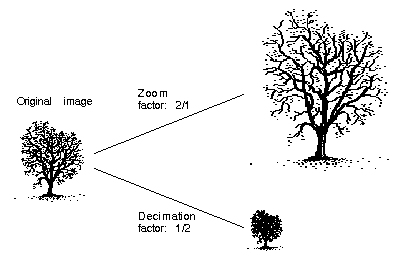
VL_ZOOM controls the expansion or decimation of the video image. Values greater than one expand the video; values less than one perform decimation. Figure 2-1 illustrates zooming and decimation.
| Note: OCTANE Digital Video screen drain nodes support the full range of VL_ZOOM (7/1, 6/1, 5/1, 4/1, 3/1, 2/1, 1/1, 1/2, 1/3, 1/4, 1/5, 1/6, 1/7, 1/8). Screen source nodes support 1/1 and 1/2. The texture node supports decimation only. The remaining nodes do not support zoom or decimation (the ratio 1/1 only). |
VL_ZOOM takes a nonzero fraction as its argument; do not use negative values. For example, this fragment captures half-size decimation video to the screen:
val.fractVal.numerator = 1;
val.fractVal.denominator = 2;
if (vlSetControl(server, screen_path, screen_drain_node, VL_ZOOM, &val)){
   vlPerror("Unable to set zoom");
   exit(1);
}
|
| Note: For a source, zooming takes place before blending; for a drain, blending takes place before zooming. |
This fragment captures half-size decimation video to the screen, with clipping to 320 × 243 (NTSC size minus overscan):
val.fractVal.numerator = 1;
val.fractVal.denominator = 2;
if (vlSetControl(server,screen_path, screen_drain_node,
VL_ZOOM, &val))
{
    vlPerror("Unable to set zoom");
    exit(1);
}
val.xyVal.x = 320;
val.xyVal.y = 243;
if (vlSetControl(server, screen_path, screen_drain_node,
VL_SIZE, &val))
{
    vlPerror("Unable to set size");
    exit(1);
}
|
This fragment captures xsize × ysize video with as much decimation as possible, assuming the size is smaller than the video stream:
if (vlGetControl(server, screen_path, screen_source, VL_SIZE, &val))
{
   vlPerror("Unable to get size");
   exit(1);
}
if (val.xyVal.x/xsize < val.xyVal.y/ysize)
   zoom_denom = (val.xyVal.x + xsize - 1)/xsize;
else
   zoom_denom = (val.xyVal.y + ysize - 1)/ysize;
val.fractVal.numerator = 1;
val.fractVal.denominator = zoom_denom;
if (vlSetControl(server, screen_path, screen_drain_node, VL_ZOOM, &val))
{
   /* allow this error to fall through */
   vlPerror("Unable to set zoom");
}
val.xyVal.x = xsize;
val.xyVal.y = ysize;
if (vlSetControl(server, screen_path, screen_drain_node,
VL_SIZE, &val))
{
   vlPerror("Unable to set size");
   exit(1);
}
|
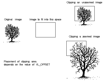
VL_SIZE controls how much of the image sent to the drain is used, that is, how much clipping takes place. This control operates on the zoomed image; for example, when the image is zoomed to half size, the limits on the size control change by a factor of 2. Figure 2-2 illustrates clipping.
For example, to display PAL video in a 320 × 243 space, clip the image to that size, as shown in the following fragment:
VLControlValue value; |
value.xyval.x=320; value.xyval.y=243; vlSetControl(vlSvr, path, drn, VL_SIZE, &value); |
| Note: Because this control is device-dependent and interacts with other controls, always check the error returns. For example, if offset is set before size and an error is returned, set size before offset. |
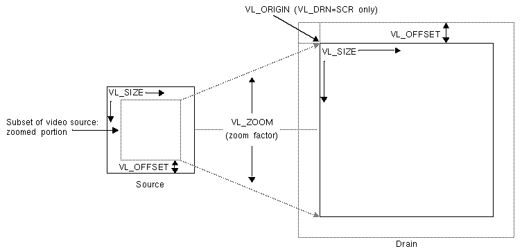
VL_OFFSET puts the upper left corner of the video data at a specific position; it sets the beginning position for the clipping performed by VL_SIZE. The values you enter are relative to the origin.
This example places the data ten pixels down and ten pixels in from the left:
VLControlValue value; |
value.xyval.x=10; value.xyval.y=10; vlSetControl(vlSvr, path, drn, VL_OFFSET, &value); |
To capture the blanking region, set offset to a negative value.
Figure 2-3 shows the relationships between the source and drain size, offset, and origin.
| Note: For memory nodes, VL_OFFSET and VL_SIZE in combination define the active region of video that is transferred to or from memory. |
An application can request that the OCTANE Digital Video option capture or play back a video stream in a number of ways. For example, the application can request that each field be placed in its own buffer, that each buffer contain an interleaved frame, or that only odd or even fields be captured. This section enumerates the capture types that the OCTANE Digital Video option supports.
A field mask is useful for identifying which fields will be captured and played back and which fields will be dropped. A field mask is a bit mask of 60 bits for NTSC or 50 bits for PAL (two fields per frame). A numeral 1 in the mask indicates that a field is captured or played back, while a zero indicates that no action occurs.
For example, the following field mask indicates that every other field will be captured or played back:
10101010101010101010... |
Capture types are as follows:
VL_CAPTURE_NONINTERLEAVED
VL_CAPTURE_INTERLEAVED (not used for texture node VL_TEX)
VL_CAPTURE_EVEN_FIELDS
VL_CAPTURE_ODD_FIELDS
VL_CAPTURE_FIELDS
These capture types apply to both VL buffers and DMbuffers.
VL_RATE determines the data transfer rate by field or frame, depending on the capture type as specified by VL_CAP_TYPE, as shown in Table 2-8.
Table 2-8. VL_RATE Values (Items per Second)
VL_CAP_TYPE Value | VL_RATE Value |
|---|---|
VL_CAPTURE_NONINTERLEAVED, VL_CAPTURE_INTERLEAVED | NTSC: 1-30 frames/second |
VL_CAPTURE_EVEN_FIELDS, | NTSC: 1-30 fields/second |
VL_CAPTURE_FIELDS | NTSC: 1-60 fields/second |
| Note: Not all rates are supported on all memory nodes; see Appendix C, “OCTANE Digital Video Color-Space Conversions,” for details. The buffer size must be set in accordance with the capture type, as listed in Table 2-10 later in this chapter. |
The VL_CAPTURE_NONINTERLEAVED capture type specifies that frame-size units are captured noninterleaved. Each field is placed in its own buffer, with the dominant field in the first buffer. If one of the fields of a frame is dropped, all fields are dropped. Consequently, an application is guaranteed that the field order is maintained; no special synchronization is necessary to ensure that fields from different frames are mixed.
The rate (VL_RATE) for noninterleaved capture is in terms of fields and must be even. For NTSC, the capture rate may be from 2-60 fields per second, and for PAL 2-50 fields per second. Because a frame is always captured as a whole, a rate of 30 fields per second results in the following field mask:
1100110011001100... |
The first bit in the field mask corresponds to the dominant field of a frame. The OCTANE Digital Video option waits for a dominant field before it starts the transfer.
If VL_CAPTURE_NONINTERLEAVED is specified for playback, similar guarantees apply as for capture. If one field is lost during playback, it is not possible to “take back” the field. The OCTANE Digital Video option resynchronizes on the next frame boundary, although black or “garbage” video might be present between the erring field and the frame boundary.
The rate during playback also follows the rules for capture. For each 1 in the mask above, a field from the VL buffer is output. During the 0 fields, the previous frame is repeated. Note that the previous frame is output, not just the last field. If there are a pair of buffers, the dominant field is placed in the first buffer.
Interleaved capture interleaves the two fields of a frame and places them in a single buffer; the order of the frames depends on the value set for VL_MGV_DOMINANCE_FIELD (see Table B-5 or Table B-6 in Appendix B for details). The OCTANE Digital Video option guarantees that the interleaved fields are from the same frame: if one field of a frame is dropped, then both are dropped.
The rate for interleaved frames is in frames per second: 1-30 frames per second for NTSC and 1-25 frames per second for PAL. A rate of 15 frames per second results in every other frame being captured. Expressed as a field mask, the following sequence is captured:
1100110011001100.... |
As with VL_CAPTURE_NONINTERLEAVED, the OCTANE Digital Video option begins processing the field mask when a dominant field is encountered.
During playback, a frame is deinterleaved and output as two consecutive fields, with the dominant field output first. If one of the fields is lost, the OCTANE Digital Video option resynchronizes to a frame boundary before playing the next frame. During the resynchronization period, black or “garbage” data may be displayed.
Rate control follows similar rules as for capture. For each 1 in the mask above, a field from the interleaved frame is output. During 0 periods, the previous frame is repeated.
This option is not applicable to the texture node VL_TEX.
In the VL_CAPTURE_EVEN_FIELDS capture type, only even (F2) fields are captured, with each field placed in its own buffer. Expressed as a field mask, the captured fields are
1010101010101010... |
The OCTANE Digital Video option begins processing this field mask when an even field is encountered.
The rate for this capture type is expressed in even fields. For NTSC, the range is 1-30 fields per second, and for PAL 1-25 fields per second. A rate of 15 fields per second (NTSC) indicates that every other even field is captured, yielding a field mask of
1000100010001000... |
During playback, the even field is repeated as both the F1 and F2 fields, until it is time to output the next buffer. If a field is lost during playback, black or “garbage” data might be displayed until the next buffer is scheduled to be displayed.
The VL_CAPTURE_ODD_FIELDS capture type works the same way as VL_CAPTURE_EVEN_FIELDS, except that only odd (F1) fields are captured, with each field placed in its own buffer. The rate for this capture type is expressed in odd fields. A rate of 15 fields per second (NTSC) indicates that every other odd field is captured. Field masks are the same as for VL_CAPTURE_EVEN_FIELDS.
The VL_CAPTURE_FIELDS capture type captures both even and odd fields and places each in its own buffer. Unlike VL_CAPTURE_NONINTERLEAVED, there is no guarantee that fields are dropped in frame units. Field synchronization can be performed by examining the UST (Unadjusted System Time), the MSC (Media Stream Count), or the dmedia info sequence number associated with each field.
The rate for this capture type is expressed in fields. For NTSC, the range is
1-60 fields per second, and for PAL 1-50 fields per second. A rate of 30 fields per second (NTSC) indicates that every other field is captured, resulting in the following field mask:
101010101010101010... |
Contrast this with the rate of 30 for VL_CAPTURE_NONINTERLEAVED, which captures every other frame.
Field mask processing begins on the first field after the transfer is started; field dominance, evenness, oddness plays no role in this capture type.
This section explains:
“Using UST, MSC, and Buffered Media Streams for Synchronization”
“Media Library Interfaces for UST and MSC”
Whenever a VL path is open in continuous mode, the Octane Digital Video board and certain other Silicon Graphics video devices continuously try to dequeue media stream samples from the path's buffer for input, or to enqueue media stream samples onto the path's buffer for output. If the buffer between the application and each device never underflows or overflows, then the application can measure and schedule the timing of input and output signals to 100% of the accuracy of the underlying device.
Occasionally, the application is held off and audio, video, or both come out late. Buffer underflow on output and overflow on input can result from the application not keeping the buffer adequately filled for the following reasons:
The application is busy with other tasks, allowing too much time between putting fields into the buffer.
Processes are subject to various interruptions (10-80 ms for some processes) under IRIX™ because
the process for filling the buffer is running at too low a priority
the process cannot get a resource from IRIX that it needs, such as memory pages
To get around this problem, a mechanism built into the VL helps keep track of data flow into and out of buffers by providing accurate timing information for each frame of video that enters or leaves the system. This mechanism, which can be called UST/MSC, produces matched pairs of two numbers:
Unadjusted System Time (UST), a time value that is used to state timing measurements to applications
Media Stream Count (MSC), a count value that identifies a particular media stream sample (a video field or frame)
The device keeps a counter called the device media stream count (device MSC), which increments by one every time the device attempts to enqueue or dequeue a media stream sample, whether or not the enqueue or dequeue attempt is successful. UST/MSC was designed to return timing information in a form that is valid whenever the buffer is not underflowing or overflowing.
The UST/MSC capability and the buffering that goes with it are appropriate for applications and devices such as movie players and digital video editing devices.
UST/MSC affords maximally accurate synchronization when scheduling cannot be guaranteed and some buffering is acceptable. Also, if scheduling becomes reliable at some later point, UST/MSC continues to function the same way with no code changes required; the buffers can be made smaller, and the result is a low-latency application with the same accurate synchronization.
Note that UST/MSC itself
does not add any latency to an application
The buffer adds latency: it increases the time the application would take to respond to some output event by changing its input (and vice versa). This solution to the synchronization problem is useful for applications in which a small latency can be sacrificed for more accuracy.
does not require that an application trade off latency for accuracy
does not require that an application use any particular size buffer
delivers the full accuracy of the underlying hardware's timing support regardless of the scheduling characteristics of the application
could be useful for graphics and texture even for low-latency applications
Following is a high-level algorithm to maintain synchronization of two buffered media streams that send data from memory to hardware outputs; a corresponding one is necessary for the other direction.
create video buffer between me and the audio output;
create audio buffer between me and the video output;
while (1)
{
   sleep until one of the buffers is getting empty;
   for (video buffer)
      {
         use UST/MSC to determine:
            “at what time (what UST) will the next video data I enqueue
            on the buffer actually go out the jack of the machine?”;
      }

   for (audio buffer)
      {
         (exact same thing as above, except for audio)
      }

   From the predicted video and audio USTs, determine
      “what is the synchronization error between the audio and video
      streams?”

   Enqueue more frames to fill up the audio and video buffer queues.
   If there is synchronization error, enqueue new frames to either skip
   frames on the stream that is behind or repeat frames on the stream
   that is ahead.
     }
}
|
The answers to the questions in the pseudocode above are obtained with three VL calls that manipulate UST and MSC and are explained in the next section.
UST/MSC calls allow you to associate a UST with a particular piece of data that just left a buffer or is about to enter a buffer. The VL calls for determining the MSC and UST—vlGetUSTMSCPair(3dm), vlGetFrontierMSC(3dm), and vlGetUSTPerMSC(3dm)—help synchronize input and output of different data streams in cases where the application is getting data from or putting data into each device via a buffer. The application is at the “frontier” end of this buffer and the devices are at the “device” end of the buffer.
vlGetUSTMSCPair() gets the timing information for each frame/field as it enters or leaves the physical jack of a device.
This call returns an atomic UST/MSC pair for the jack (specified with the VL_NODE and the VLPort for that node) for a given path that contains a VL_MEM node. The returned MSC is not guaranteed to be the one currently at the jack, nor is it even guaranteed to be the number of any media stream sample currently in the application's buffer. To relate the returned MSC to a particular item in the application's buffer, you must use vlGetFrontierMSC().
vlGetFrontierMSC() gets the frontier MSC associated with a particular VL_MEM node.
The frontier MSC, at the application end of the media stream, is the MSC of the next item that the application removes from or puts into the buffer.
vlGetUSTPerMSC() gets the time spacing of fields/frames in a path (the nominal average UST time elapsed between media stream samples in a given VLPath that includes a VL_MEM node).
These calls are used for extrapolating a UST/MSC pair as shown in vlGetFrontierMSC(). For other types of media streams, a similar mechanism extrapolates the UST/MSC pair; for example, for audio, use equivalent AL calls.
Once you have calculated the extrapolated UST/MSC pairs for both media streams, you can determine the synchronization error. The difference in the audio and video USTs for matching frame numbers is the amount they are out of sync. To resynchronize them, you must enqueue new frames to either skip frames on the stream that is behind or repeat frames on the stream that is ahead. The number of frames to be skipped or repeated is the difference in USTs divided by the frame rate.
To use UST/MSC, the application must have separate handles for each separate piece of data coming in or going out of some kind of buffer. The application can use these handles to specify, for example, a particular frame to output or pixels of a particular field to get.
| Note: For complete details, including syntax, code examples, and caveats, see the references pages for these calls. |
To set up a window for live video, follow these steps, as outlined in the example program simplev2s.c.
Open an X display window; for example:
if (!(dpy = XOpenDisplay("")))
    exit(1);
Connect to the video daemon; for example:
if (!(vlSvr = vlOpenVideo("")))
     exit(1);
Create a window to show the video; for example:
vwin = XCreateSimpleWindow(dpy, RootWindow(dpy, 0), 10,
    10, 640, 486, 0,
    BlackPixel(dpy,DefaultScreen(dpy)),
    BlackPixel(dpy, DefaultScreen(dpy));
XMapWindow(dpy, vwin);
XFlush(dpy);
Create a source node on a video device and a drain node on the screen; for example:
src = vlGetNode(vlSvr, VL_SRC, VL_VIDEO, VL_ANY);
drn = vlGetNode(vlSvr, VL_DRN, VL_SCREEN, VL_ANY);
Create a path on the first device that supports it; for example:
if ((path = vlCreatePath(vlSvr, VL_ANY, src, drn)) < 0)
    exit(1);
Set up the hardware for the path and define the path use; for example:
vlSetupPaths(vlSvr, (VLPathList)&path, 1, VL_SHARE,
    VL_SHARE);
Set the X window to be the drain; for example:
val.intVal = vwin;
vlSetControl(vlSvr, path, drn, VL_WINDOW, &val);
Get X and VL into the same coordinate system; for example:
XTranslateCoordinates(dpy, vwin, RootWindow(dpy,
    DefaultScreen(dpy)), 0, 0,&x, &y, &dummyWin);
Set the live video to the same location and size as the window; for example:
val.xyVal.x = x;
val.xyVal.y = y;
vlSetControl(vlSvr, path, drn, VL_ORIGIN, &val);
XGetGeometry(dpy, vwin, &dummyWin, &x, &y, &w, &h, &bw,
   &d);
val.xyVal.x = w;
val.xyVal.y = h;
vlSetControl(vlSvr, path, drn, VL_SIZE, &val);
Begin the data transfer:
vlBeginTransfer(vlSvr, path, 0, NULL);
Wait until the user finishes; for example:
printf("Press return to exit.\n");
c = getc(stdin);
End the data transfer, clean up, and exit:
vlEndTransfer(vlSvr, path);
vlDestroyPath(vlSvr, path);
vlCloseVideo(vlSvr);
“Using Buffers”
“Transferring Video Data Using DMBuffers”
“Transferring Video Data Using VL Buffers”
The VL supports two buffering mechanisms for capturing or playing back video:
VL buffers: the original buffering mechanism supported by the VL and specific to it
Digital Media Buffers (DMbuffers): a buffering mechanism allowing video data to be exchanged among video, compression, and graphics devices
For OCTANE, this buffering mechanism is supported by the Video, Image Converter (dmIC), and Movie libraries. It is available with IRIX 6.4 and subsequent releases.
| Note: For complete information on DMbuffers and digital media image converters, see the Digital Media Programming Guide. |
In general, VL buffers and DMbuffers differ in the following ways:
buffer structure
VL buffers are modeled after a ring buffer. The order of segments (buffers) in the ring is inflexible, and care must be taken to ensure that items are obtained and returned in the same order. For example, buffers obtained with vlGetNextValid() must be returned using vlPutFree() in the same order. Order and allocation of ring segments are intricately related.
All operations on a VL buffer operate in FIFO order. That is, the first element retrieved by vlGetNextValid() is the first returned by vlPutFree(). This function does not take an element as a parameter and always puts back the oldest outstanding element.
DMbuffers, in contrast, are contained in a DMbufferpool. The pool itself is unordered; buffers can be obtained from and returned to the pool in any order. Ordering is achieved by a first-in-first-out queue, and is maintained only while the buffers are in the queue. The application or library is free to impose any processing order on buffers, once they have been dequeued.
buffer size and alignment
The Video Library is responsible for ensuring that VL buffers are of the appropriate size and alignment for the video device, and for allocating the buffers in the vlCreateBuffer() call. Except in rare cases, applications cannot modify these attributes to suit the needs of another library or device.
Because DMbuffers can be used with libraries and devices besides video, the application queries each library for its buffering requirements. The exact DMbufferpool requirements are the union of all requested constraints and are enforced when the pool is created. For example, if one library requests alignment on 4K boundaries and another requests alignment on 16K boundaries, the 16K alignment is used. By specifying its own pool requirements list, the application can set minimum buffer sizes (such as for in-place processing of video) or cache policies.
buffers and memory nodes
With VL buffers, a particular ring buffer is strictly tied to a particular memory node; a DMbufferpool is not necessarily tied to a memory node. A memory source node can receive DMbuffers allocated from any DMbufferpool that meets the memory node's pool requirements. Memory drain nodes obtain DMbuffers from a DMbufferpool specified by the application; this pool is fixed for the duration of a transfer.
Each buffering mechanism has a set of API functions for creating, registering, and manipulating buffers. A mismatch between a buffer mechanism and an API call, for example, applying a VL buffer call to a DMbuffer, results in a VLAPIConflict error return.
Applications can use either VL buffers or DMbuffers, as long as a memory node is used with only one buffering mechanism at a time. If an application uses multiple memory paths, each path can use a different buffering mechanism. To switch buffering mechanisms, the VL path should be torn down and reconstructed.
Table 2-9 shows correspondences between VL buffer and DMbuffer API functions.
Table 2-9. VL Buffer and DMBuffer API Functions
VL Buffer API | dmBuffer API |
|---|---|
vlCreateBuffer() | dmBufferCreatePool() |
vlPutValid() | vlDMBufferPutValid() |
vlRegisterBuffer() | vlDMBufferPoolRegister() |
vlDeregisterBuffer() | No equivalent |
vlPutFree() | dmBufferFree() |
vlGetNextValid() | vlDMBufferGetValid() |
vlGetLatestValid() | No equivalent |
vlGetFilled() | vlGetFilledByNode() |
vlDestroyBuffer() | dmBufferDestroyPool() |
vlBufferGetFd() | dmBufferGetPoolFD() dmBufferSetPoolSelectSize() vlNodeGetFd() |
vlBufferAdvise() | dmSetPoolDefaults() |
vlBufferReset() | vlDMBufferNodeReset() |
vlBufferDone() | Not applicable |
The DMbuffer is created through the dmBufferCreatePool() routine and is associated with a memory node by the dmPoolRegister() routine.
When the OCTANE Digital Video option transfers data from the Video Library to an application, it places data in a buffer element and marks the element as valid. The application can retrieve the element through the vlDMBufferGetValid() routine. When the application is done, it uses the dmBufferFree() routine to alert the video device that the buffer element can be reused. For complete details on using DMbuffers, see Chapter 5 of the Digital Media Programming Guide (007-1799-060 or later).
This section explains
Before a DMbufferpool is created, you must obtain the pool requirements of any library that will interact with the pool. Pool requirements are maintained in a DMparams list, created using dmParamsCreate() and initialized by calling dmBufferSetPoolDefaults(). See Chapter 3 in the Digital Media Programming Guide for an overview of DMparams. The function prototype for this call is
DMstatus dmBufferSetPoolDefaults(DMparams *poolParams, int bufferCount, int bufferSize, DMboolean cacheable, DMboolean mapped) |
where
| poolParams | specifies the DMparams list to use for gathering pool requirements | |
| bufferCount | specifies the number of buffers the pool should contain | |
| bufferSize | specifies the size of each buffer in the pool | |
| cacheable | specifies whether buffers allocated from the pool can be cached (DM_TRUE) or not (DM_FALSE). For more information on caching, see“Caching” in Chapter 6. | |
| mapped | specifies whether the memory allocated for the pool should be mapped as soon as the pool is created (TRUE), or only when dmBufferMapData() is called (FALSE) If an application requires a pointer to buffer contents, for example, to process or store the contents to disk, then the pool should be created mapped. This option improves the performance of the dmBufferMapData() call. |
The Video Library pool requirements are obtained by calling vlDMBufferGetParams() on a memory node:
int vlDMBufferGetParams(VLServer svr, VLPath path, VLNode node, DMparams *params) |
where
| svr | names the server to which the path is connected | |
| path | specifies the data path containing the memory node | |
| node | specifies the memory node with which the DMbufferpool will be used | |
| params | specifies the pool requirements list |
As with similar calls in other libraries, vlDMBufferGetParams takes as input a DMparams list initialized by dmBufferSetPoolDefaults, and possibly other libraries' pool requirements functions. On output, the Video Library's requirements are merged with the input requirements.
After all libraries that will use the pool have been queried for their requirements, the application can create a DMbufferpool by calling dmBufferCreatePool. Its function prototype is:
DMstatus dmBufferCreatePool(const DMparams *poolParams, DMbufferpool *returnPool) |
where
| poolParams | specifies the requirements for the pool | |
| returnPool | points to a location where the DMbufferpool handle will be stored |
If the application captures video data, it specifies the DMbufferpool the memory node should use by calling vlDMBufferPoolRegister:
int vlDMBufferPoolRegister(VLServer svr, VLPath path, VLNode node, DMbufferpool pool) |
where
| svr | specifies the server that the path is attached to | |
| path | specifies the path containing the memory node | |
| node | specifies the memory node | |
| pool | specifies the pool that the memory node should use |
When the video device is ready to capture a new frame or field, it will allocate a DMbuffer from the specified pool, place the field or frame in it, then send the buffer to the application.
To begin data transfer (for either type of buffer), use vlBeginTransfer(). Its function prototype is
int vlBeginTransfer(VLServer vlSvr, VLPath path, int count,
      VLTransferDescriptor* xferDesc)
|
where
| vlSvr | names the server to which the path is connected | |
| path | specifies the data path | |
| count | specifies the number of transfer descriptors | |
| xferDesc | specifies an array of transfer descriptors |
Tailor the data transfer by means of transfer descriptors. Multiple transfer descriptors are supplied; they are executed in order. The transfer descriptors are
| xferDesc.mode | Transfer method:
| |
| xferDesc.count | Number of frames to transfer; if mode is VL_TRANSFER_MODE_CONTINUOUS, this value is ignored. | |
| xferDesc.delay | Number of frames from the trigger at which data transfer begins. | |
| xferDesc.trigger | Set of events to trigger on; an event mask. This transfer descriptor is always required. VLTriggerImmediate specifies that transfer begins immediately, with no pause for a trigger event. VLDeviceEvent specifies an external trigger. If xferDesc is NULL, then VL_TRIGGER_IMMEDIATE and VL_TRANSFER_CONTINUOUS_MODE are assumed and one transfer is performed. |
This example fragment transfers the entire contents of the buffer immediately.
xferDesc.mode = VL_TRANSFER_MODE_DISCRETE; |
xferDesc.count = imageCount; xferDesc.delay = 0; xferDesc.trigger = VLTriggerImmediate; |
This fragment shows the default descriptor, which is the same as passing in a null for the descriptor pointer. Transfer begins immediately; count is ignored.
xferDesc.mode = VL_TRANSFER_MODE_CONTINUOUS; |
xferDesc.count = 0; xferDesc.delay = 0; xferDesc.trigger = VLTriggerImmediate; |
After the transfer has been started, captured video may be retrieved using vlDMBufferGetValid:
int vlDMBufferGetValid(VLServer svr, VLPath path, VLNode node, DMbuffer* dmbuffer) |
where
| svr | specifies the server the path is attached to | |
| path | specifies the path on which data is received from | |
| node | specifies the memory drain node data is received from | |
| dmbuffer | points to a location where a DMbuffer handle is stored |
The DMbuffer handle returned by vlDMBufferGetValid is an opaque reference to the captured video. dmBufferMapData can be used to obtain a pointer to the actual image data so that it can be processed or written to disk. dmBufferMapData does not have to be called if the buffer will be directly sent to another device or library.
Applications can use vlDMBufferPutValid to send buffers to a video device:
int vlDMBufferPutValid(VLServer svr, VLPath path, VLNode node, DMbuffer dmbuffer) |
where
| svr | specifies the server to which the path is attached | |
| path | specifies the path on which video is sent | |
| node | specifies the memory source node to send the buffer to | |
| dmbuffer | specifies the buffer to send |
The DMbuffer may have been obtained from another library, such as dmIC, or generated by the application itself. See Chapter 5 in the Digital Media Programming Guide for an explanation of how to allocate a DMbuffer from a DMbufferpool.
Once the application is done with a buffer, it should call dmBufferFree to indicate that it no longer intends to use the buffer. After all users of a buffer have called dmBufferFree on it, the buffer is considered free to be reallocated. The Video Library never implicitly releases the application's access to a buffer. Consequently, an application can send the same buffer to a memory node multiple times, or hold a captured image for an indefinite period.
The processes for data transfer using VL buffers are as follows:
Each process is explained separately.
Once you have specified frame parameters in a transfer involving memory (or have determined to use the defaults), create a VL buffer for the video data. In this case, video data is frames or fields, depending on the capture type:
frames if the capture type is VL_CAPTURE_NONINTERLEAVED
fields if the capture type is anything else
VL buffers provide a way to read and write varying sizes of video data. A frame of data consists of the actual frame data and an information structure describing the underlying data, including device-specific information.
When a VL buffer is created, constraints are specified that control the total size of the data segment and the number of frame or field buffers (sectors) to allocate. A head and a tail flag are automatically set in a VL buffer so that the latest frame can be accessed. A sector is locked down if it is not called; that is, it remains locked until it is read. When the VL buffer is written to and all sectors are occupied, data transfer stops. The sector last written to remains locked down until it is released.
All sectors in a VL buffer must be of the same size, which is the value returned by vlGetTransferSize(). Its function prototype is
long vlGetTransferSize(VLServer vlSvr, VLPath path) |
For example:
transfersize = vlGetTransferSize(vlSvr, path); |
where transfersize is the size of the data in bytes.
To create a VL buffer for the frame data, use vlCreateBuffer(). Its function prototype is
VLBuffer vlCreateBuffer(VLServer vlSvr, VLPath path, VLNode node,
     int numFrames)
|
where
| VLBuffer | is the handle of the buffer to be created | |
| vlSvr | names the server to which the path is connected | |
| path | specifies the data path | |
| node | specifies the memory node containing data to transfer to or from the VL buffer | |
| numFrames | specifies the number of sectors in the buffer (fields or frames, depending on the capture type) |
For example:
buf = vlCreateBuffer(vlSvr, path, src, 1); |
Table 2-10 shows the relationship between capture type and minimum VL buffer size.
Table 2-10. Buffer Size Requirements
Capture Type | Minimum Sectors for Capture | Minimum Sectors for Playback |
|---|---|---|
VL_CAPTURE_NONINTERLEAVED | 2 | 4 |
VL_CAPTURE_INTERLEAVED | 1 | 2 |
VL_CAPTURE_EVEN_FIELDS | 1 | 2 |
VL_CAPTURE_ODD_FIELDS | 1 | 2 |
VL_CAPTURE_FIELDS | 1 | 2 |
| Note: For VGI1 memory nodes, real-time memory or video transfer can be performed only as long as buffer sectors are available to the OCTANE Digital Video device. |
Use vlRegisterBuffer() to register the VL buffer with the data path. Its function prototype is
int vlRegisterBuffer(VLServer vlSvr, VLPath path,
     VLNode memnodeid, VLBuffer buffer)
|
where
| vlSvr | names the server to which the path is connected | |
| path | specifies the data path | |
| memnodeid | specifies the memory node ID | |
| buffer | specifies the VL buffer handle |
For example:
vlRegisterBuffer(vlSvr, path, drn, Buffer); |
Start data transfer the same way as for DMbuffers; see “Starting Data Transfer” in “Transferring Video Data Using DMbuffers.”
If your application uses a VL buffer, use various VL calls for reading frames, getting pointers to active buffers, freeing buffers, and other operations. Table 2-11 lists the buffer-related calls.
Table 2-11. Buffer-Related Calls
Call | Purpose |
|---|---|
vlGetNextValid() | Returns a handle on the next valid frame or field of data |
vlGetLatestValid() | Reads only the most current frame or field in the buffer, discarding the rest |
vlPutValid() | Puts a frame or field into the valid list (memory to video) |
vlPutFree() | Puts a valid frame or field back into the free list (video to memory) |
vlGetNextFree() | Gets a free buffer into which to write data (memory to video) |
vlBufferDone() | Informs you if the buffer has been vacated |
vlBufferReset() | Resets the buffer so that it can be used again |
Figure 2-4 illustrates the difference between vlGetNextValid() and vlGetLatestValid(), and their interaction with vlPutFree().
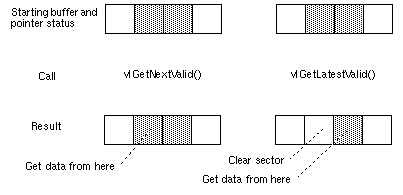
Table 2-12 lists the calls that extract information from a buffer.
Table 2-12. Calls for Extracting Data From a Buffer
Call | Purpose |
|---|---|
vlGetActiveRegion() | Gets a pointer to the data region of the buffer (video to memory); called after vlGetNextValid() and vlGetLatestValid() |
vlGetDMediaInfo() | Gets a pointer to the DMediaInfo structure associated with a frame; this structure contains timestamp and field count information |
vlGetImageInfo() | Gets a pointer to the DMImageInfo structure associated with a frame; this structure contains image size information |
| Caution: None of these calls has count or block arguments; appropriate calls in the application must deal with a NULL return in cases of no data being returned. |
In summary, for video-to-memory transfer, use
buffer = vlCreateBuffer(vlSvr, path, memnode1); vlRegisterBuffer(vlSvr, path, memnode1, buffer); vlBeginTransfer(vlSvr, path, 0, NULL); info = vlGetNextValid(vlSvr, buffer); /* OR vlGetLatestValid(vlSvr, buffer); */ dataptr = vlGetActiveRegion(vlSvr, buffer, info); /* use data for application */ … vlPutFree(vlSvr, buffer); |
For memory-to-video transfer, use
buffer = vlCreateBuffer(vlSvr, path, memnode1); vlRegisterBuffer(vlSvr, path, memnode1, buffer); vlBeginTransfer(vlSvr, path, 0, NULL); buffer = vlGetNextFree(vlSvr, buffer, bufsize); /* fill buffer with data */ … vlPutValid(vlSvr, buffer); |
To read the frames to memory from the buffer, use vlGetNextValid() to read all the frames in the buffer or get a valid frame of data. Its function prototype is
VLInfoPtr vlGetNextValid(VLServer vlSvr, VLBuffer vlBuffer) |
Use vlGetLatestValid() to read only the most current frame in the buffer, discarding the rest. Its function prototype is
VLInfoPtr vlGetLatestValid(VLServer vlSvr, VLBuffer vlBuffer) |
After removing interesting data, return the buffer for use with vlPutFree() (video to memory). Its function prototype is
int vlPutFree(VLServer vlSvr, VLBuffer vlBuffer) |
To send frames from memory to video, use vlGetNextFree() to get a free buffer to which to write data. Its function prototype is
VLInfoPtr vlGetNextFree(VLServer vlSvr, VLBuffer vlBuffer,
      int size)
|
After filling the buffer with the data you want to send to video output, use vlPutValid() to put a frame into the valid list for output to video (memory to video). Its function prototype is
int vlPutValid(VLServer vlSvr, VLBuffer vlBuffer) |
| Caution: These calls do not have count or block arguments; appropriate calls in the application must deal with a NULL return in cases of no data being returned. |
To get DMediaInfo and Image Data from the buffer, use vlGetActiveRegion() to get a pointer to the active buffer. Its function prototype is
void * vlGetActiveRegion(VLServer vlSvr, VLBuffer vlBuffer,
     VLInfoPtr ptr)
|
Use vlGetDMediaInfo() to get a pointer to the DMediaInfo structure associated with a frame. This structure contains timestamp and field count information. The function prototype for this call is
DMediaInfo * vlGetDMediaInfo(VLServer vlSvr, VLBuffer vlBuffer,
     VLInfoPtr ptr)
|
Use vlGetImageInfo() to get a pointer to the DMImageInfo structure associated with a frame. This structure contains image size information. The function prototype for this call is
DMImageInfo * vlGetImageInfo(VLServer vlSvr, VLBuffer vlBuffer,
     VLInfoPtr ptr)
|
To end data transfer for either VL buffers or DMbuffers, use vlEndTransfer(). Its function prototype is
int vlEndTransfer(VLServer vlSvr, VLPath path) |
A discrete transfer is finished when the last frame of the sequence is output. The two types of memory nodes behave differently at the last frame:
The CC1 memory source stops transferring data from main memory to the OCTANE Digital Video device, but continues to output to video the last frame transferred, which is held in a framebuffer associated with the CC1 memory node.
The VGI1 memory nodes have no associated framebuffer and consequently emit black video output after a transfer (discrete or continuous) has been completed.
To accomplish the necessary cleanup to exit gracefully, use the following functions:
The function prototype for vlDeregisterBuffer() is
int vlDeregisterBuffer(VLServer vlSvr, VLPath path,
    VLNode memnodeid, VLBuffer ringbufhandle)
|
where
| vlSvr | is the server handle | |
| path | is the path handle | |
| memnodeid | is the memory node ID | |
| ringbufhandle | is the VL buffer handle |
The function prototypes for vlDestroyPath(), vlDestroyBuffer(), dmBuffer(), and vlCloseVideo() are, respectively
int vlDestroyPath(VLServer vlSvr, VLPath path) int vlDestroyBuffer(VLServer vlSvr, VLBuffer vlBuffer) int vlGetFilledByNode(VLServer vlSvr, VLPath path, VLNode node); int vlDMBufferNodeReset(VLServer vlSvr, VLPath path, VLNode node); int vlCloseVideo(VLServer vlSvr) |
where vlSvr specifies the server to which the application is attached, and path and node identify the memory node on which information is requested.
This example ends a data transfer that used a buffer:
vlEndTransfer(vlSvr, path); vlDeregisterBuffer(vlSvr, path, memnodeid, buffer); vlDestroyPath(vlSvr, path); vlDestroyBuffer(vlSvr, buffer); vlCloseVideo(vlSvr); |
For DMbuffers, vlDMBufferPoolDeregister disassociates a DMbufferpool from a memory node. It should be called to clean up the memory node or allow a new DMbufferpool to be used after a transfer has been stopped.
Once the application is done with a DMbufferpool, the pool should be destroyed using the dmBufferDestroyPool call.
The directory /usr/share/src/dmedia/video/vl includes a number of example programs. These programs illustrate how to create simple video applications; for example:
a simple screen application: simplev2s.c
This program shows how to send live video to the screen.
a video-to-memory frame grab: simplegrab.c
This program demonstrates video frame grabbing.
a memory-to-video frame output simplem2v.c
This program sends a frame to the video output.
a continuous frame capture: simpleccapt.c
This program demonstrates continuous frame capture.
| Note: To simplify the code, these examples do not check returns. However, you should always check returns. |
See Chapter 4 for a description of eventex.c and Chapter 7 for descriptions of simpleblend.c and simplewipe.c.
The directory /usr/share/src/dmedia/video/vl/OpenGL contains three example OpenGL programs:
These programs are the OpenGL equivalents of the programs with the same names in /usr/share/src/dmedia/video/vl.