To see this information in a web browser, click Hardware Central . (If your web browser is not loaded, it takes a few seconds to load.) Or, if you are viewing this on a remote system, see the sections below.
This section contains cable pinout information for the following O2 ports:
Table A-1 shows cable pinout assignments for the serial ports.
Table A-1. Serial Port Pinout Assignments
Pin | Assignment | Description |
|---|---|---|
1 | DCD | Data Carrier Detect |
2 | RD | Receive Data |
3 | TD | Transmit Data |
4 | DTR | Data Terminal Ready |
5 | SG | Signal Ground |
6 | DSR | Data Set Ready |
7 | RTS | Request to Send |
8 | CTS | Clear to Send |
9 | RI | Ring Indicator |
Table A-2 shows the cable pinout assignments for the IEEE 1284-C parallel port for Silicon Graphics' floppy drive or for a printer. (The floppy drive has an additional connector for a printer.)
Table A-2. Parallel Port (IEEE 1284-C) Pinout Assignments
Pin | Assignment | Pin | Assignment |
|---|---|---|---|
1 | BUSY | 19 | SIGNAL GROUND (BUSY) |
2 | SELECT | 20 | SIGNAL GROUND (SELECT) |
3 | nACK | 21 | SIGNAL GROUND (nACK) |
4 | nFAULT | 22 | SIGNAL GROUND (nFAULT) |
5 | pERROR | 23 | SIGNAL GROUND (pERROR) |
6 | DATA 1 | 24 | SIGNAL GROUND (DATA 1) |
7 | DATA 2 | 25 | SIGNAL GROUND (DATA 2) |
8 | DATA 3 | 26 | SIGNAL GROUND (DATA 3) |
9 | DATA 4 | 27 | SIGNAL GROUND (DATA 4) |
10 | DATA 5 | 28 | SIGNAL GROUND (DATA 5) |
11 | DATA 6 | 29 | SIGNAL GROUND (DATA 6) |
12 | DATA 7 | 30 | SIGNAL GROUND (DATA 7) |
13 | DATA 8 | 31 | SIGNAL GROUND (DATA 8) |
14 | nINIT | 32 | SIGNAL GROUND (nINIT) |
15 | nSTROBE | 33 | SIGNAL GROUND (nSTROBE) |
16 | nSELECTIN | 34 | SIGNAL GROUND (nSELECTIN) |
17 | nAUTOFD | 35 | SIGNAL GROUND (nAUTOFD) |
18 | HOST LOGIC HIGH | 36 | PERIPHERAL LOGIC HIGH |
Table A-3 shows the cable pinout assignments for the Ethernet 10-Base T/100-Base T port.
Table A-3. Ethernet 10-BASE T/100-Base T Port Pinout Assignments
Pin | Assignment |
|---|---|
1 | TRANSMIT+ |
2 | TRANSMIT– |
3 | RECEIVE+ |
4 | (Reserved) |
5 | (Reserved) |
6 | RECEIVE– |
7 | (Reserved) |
8 | (Reserved) |
Table A-4 shows the cable pinout assignments for the keyboard and mouse ports.
Table A-4. Keyboard and Mouse Ports (6-pin MINIDIN) Pinout Assignments
Pin | Assignment |
|---|---|
1 | KEYBOARD/MOUSE DATA |
2 | (Reserved) |
3 | GROUND |
4 | KEYBOARD/MOUSE POWER (+5V) |
5 | KEYBOARD/MOUSE CLOCK |
6 | (Reserved) |
Table A-5 shows the cable pinout assignments for the SCSI port.
Table A-5. SCSI Port Pinout Assignments
Pin | Assignment | Pin | Assignment |
|---|---|---|---|
1 | GROUND | 35 | -DB(12) |
2 | GROUND | 36 | -DB(13) |
3 | GROUND | 37 | -DB(14) |
4 | GROUND | 38 | -DB(15) |
5 | GROUND | 39 | -DB(P1) |
6 | GROUND | 40 | -DB(0) |
7 | GROUND | 41 | -DB(1) |
8 | GROUND | 42 | -DB(2) |
9 | GROUND | 43 | -DB(3) |
10 | GROUND | 44 | -DB(4) |
11 | GROUND | 45 | -DB(5) |
12 | GROUND | 46 | -DB(6) |
13 | GROUND | 47 | -DB(7) |
14 | GROUND | 48 | -DB(P) |
15 | GROUND | 49 | GROUND |
16 | GROUND | 50 | GROUND |
17 | TERMPWR | 51 | TERMPWR |
18 | TERMPWR | 52 | TERMPWR |
19 | OPEN | 53 | OPEN |
20 | GROUND | 54 | GROUND |
21 | GROUND | 55 | -ATN |
22 | GROUND | 56 | GROUND |
23 | GROUND | 57 | -BSY |
24 | GROUND | 58 | -ACK |
25 | GROUND | 59 | -RST |
26 | GROUND | 60 | -MSG |
27 | GROUND | 61 | -SEL |
28 | GROUND | 62 | -C/D |
29 | GROUND | 63 | -REQ |
30 | GROUND | 64 | -I/O |
31 | GROUND | 65 | -DB(8) |
32 | GROUND | 66 | -DB(9) |
33 | GROUND | 67 | -DB(10) |
34 | GROUND | 68 | -DB(11) |
Figure A-1 shows the cable pinout assignments for the audio ports.
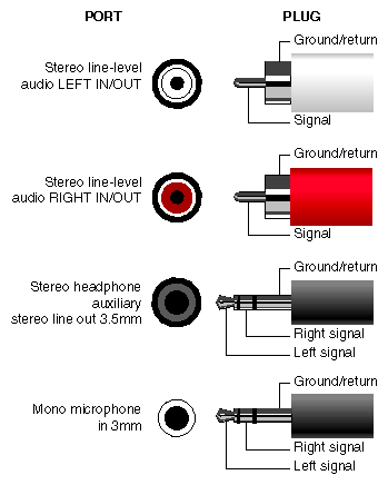
Table A-6 shows the cable pinout assignments for the analog composite video in and out ports (RCA jack, NTSC or PAL formats)
Table A-6. Analog Composite Video Port(RCA, NTSC or PAL Formats) Pinout Assignments
Pin | Assignment |
|---|---|
2 (sleeve) | GROUND |
3 (tip) | DATA |
Figure A-2 shows the cable pinout assignments for the analog s-video in and out port. (The video option is not available on all models).
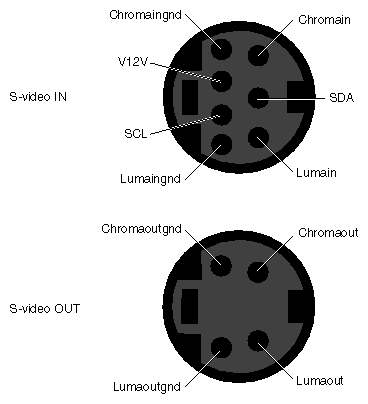
Table A-7 shows the cable pinout assignments for the digital video in/out port for the Silicon Graphics O2Cam digital video camera. (The video option is not available on all models).
Table A-7. Digital Video Port for the O2Cam Camera
Pin | Assignment | Pin | Assignment |
|---|---|---|---|
1 | +5V | 35 | +5V |
2 | I2C_SCL | 36 | I2C_SDA |
3 | GPI IN | 37 | GPI OUTGND |
4 | GPI INGND | 38 | GPI OUT |
5 | OUTDATACLK | 39 | CAM MIC POS |
6 | OUTDATACLKGND | 40 | CAM MIC NEG |
7 | INDATA9GND | 41 | OUTDATA9 |
8 | INDATA9 | 42 | OUTDATA9GND |
9 | INDATA8GND | 43 | OUTDATA8 |
10 | INDATA8 | 44 | OUTDATA8GND |
11 | INDATA7GND | 45 | OUTDATA7 |
12 | INDATA7 | 46 | OUTDATA7GND |
13 | INDATA6GND | 47 | OUTDATA6 |
14 | INDATA6 | 48 | OUTDATA6GND |
15 | INDATA5GND | 49 | OUTDATA5 |
16 | INDATA5 | 50 | OUTDATA5GND |
17 | INDATA4GND | 51 | OUTDATA4 |
18 | INDATA4 | 52 | OUTDATA4GND |
19 | INDATA3GND | 53 | OUTDATA3 |
20 | INDATA3 | 54 | OUTDATA3GND |
21 | INDATA2GND | 55 | OUTDATA2 |
22 | INDATA2 | 56 | OUTDATA2GND |
23 | INDATA1GND | 57 | OUTDATA1 |
24 | INDATA1 | 58 | OUTDATA1GND |
25 | INDATA0GND | 59 | OUTDATA0 |
26 | INDATA0 | 60 | OUTDATA0GND |
27 | INDATACLK | 61 | RESERVED |
28 | INDATACLKGND | 62 | RESERVED |
29 | RESERVED | 63 | RESERVED |
30 | -12V | 64 | +12V |
31 | RESERVED | 65 | RESERVED |
32 | RESERVED | 66 | RESERVED |
33 | RESERVED | 67 | RESERVED |
34 | RESERVED | 68 | RESERVED |
Table A-8 shows the cable pinout assignments for the O2 monitor DSUB15 port.
Table A-8. Monitor Port (DSUB15) Pinout Assignments
Pin | Assignment |
|---|---|
1 | RED |
2 | GREEN (complete sync in some modes) |
3 | BLUE |
4 | RESERVED |
5 | GROUND |
6 | RED RETURN |
7 | GREEN RETURN |
8 | BLUE RETURN |
9 | +5V, limited current |
10 | GROUND |
11 | RESERVED |
12 | IIC DATA |
13 | HORIZONTAL SYNC |
14 | VERTICAL SYNC |
15 | IIC CLOCK |
Table A-9 shows the cable pinout assignments for the stereo view port on the optional Presenter 1280/stereo view adapter board..
Table A-9. Optional Stereo View Port Pin Assignments
Pin | Assignment |
|---|---|
1 | STEREO POWER (+12V, 0.5A) |
2 | STEREO GROUND |
3 | VERTICAL - ODD FIELD |
Table A-10 shows the cable pinout assignments for the optional Presenter 1280 adapter board.
Table A-10. Presenter 1280 Monitor Port (Optional)
Pin | Assignment | Pin | Assignment |
|---|---|---|---|
1 | RED_P[0] | 35 | RED_P[1] |
2 | RED_N[0] | 36 | RED_N[1] |
3 | RED_P[2] | 37 | RED_P[3] |
4 | RED_N[2] | 38 | RED_N[3] |
5 | RED_P[4] | 39 | RED_P[5] |
6 | RED_N[4] | 40 | RED_N[5] |
7 | RED_P[6] | 41 | RED_P[7] |
8 | RED_N[6] | 42 | RED_N[7] |
9 | GRN_P[0] | 43 | GRN_P[1] |
10 | GRN_N[0] | 44 | GRN_N[1] |
11 | GRN_P[2] | 45 | GRN_P[3] |
12 | GRN_N[2] | 46 | GRN_N[3] |
13 | GRN_P[4] | 47 | GRN_P[5] |
14 | GRN_N[4] | 48 | GRN_P[5] |
15 | GRN_P[6] | 49 | GRN_P[7] |
16 | GRN_N[6] | 50 | GRN_P[7] |
17 | BLUE_P[0] | 51 | BLUE_P[1] |
18 | BLUE_N[0] | 52 | BLUE_N[1] |
19 | BLUE_P[2] | 53 | BLUE_P[3] |
20 | BLUE_N[2] | 54 | BLUE_N[3] |
21 | BLUE_P[4] | 55 | BLUE_P[5] |
22 | BLUE_N[4] | 56 | BLUE_N[5] |
23 | BLUE_P[6] | 57 | BLUE_P[7] |
24 | BLUE_N[6] | 58 | BLUE_N[7] |
25 | FP_PIXEL_CLK_P | 59 | FP_HSYNC_CLK_P |
26 | FP_PIXEL_CLK_N | 60 | FP_HSYNC_CLK_N |
27 | FP_VSYNC_CLK_P | 61 | FP_AUDIO_R-P |
28 | FP_VSYNC_CLK_N | 62 | FP_AUDIO_R-N |
29 | POWERGOOD | 63 | FP_AUDIO_L-P |
30 | RESERVED | 64 | FP_AUDIO_L-N |
31 | CABLE_GND | 65 | CABLE_GND |
32 | CABLE_GND | 66 | CABLE_GND |
33 | FP_12C_DATA | 67 | FP_12C_CLK |
34 | CABLE_GND | 68 | CABLE_GND |
This section contains cable pinout information for serial cables that you can connect to your O2 workstation. It also describes Silicon Graphics' serial port converters. The following topics are covered:
For serial printers and dumb terminals, use a 3-wired standard PC cable. Table A-11 shows the cable connector pinout assignments for this cable.
 | Note: For a 3-wire cable and no hardware flow control modem, you must use the /dev/ttyd* command devices in the configuration files. For more detailed information, see the serial man page. To access the man page, from the Toolchest choose Help > InfoSearch and select “Man pages.” Or place the cursor in the console window and type |
Table A-11. Cable Pinout Assignments for the Printer/Dumb Terminal Serial Cable
Signal Description | Pin Number | Pin Number |
|---|---|---|
| 1 | NOT CONNECTED |
RXD | 2 | 2 |
TXD | 3 | 3 |
| 4 | NOT CONNECTED |
GND | 5 | 7 |
| 6 | NOT CONNECTED |
| 7 | NOT CONNECTED |
| 8 | NOT CONNECTED |
| 9 | NOT CONNECTED |
Use a full-handshake (includes RTS and CTS) PC modem serial cable for a modem with RTS/CTS flow control. Table A-12 shows the cable connector pin assignments for this cable.
You can use this cable for all serial devices except those that do not need RTS flow control. Devices like serial printers and dumb terminals that do not need RTS flow control can still be used with this cable provided that a null modem adapter is added to one end of the cable. You can purchase the full-handshake PC modem serial cable from Silicon Graphics or your local service provider.
| Note: If you are attaching a modem with modem signals and RTS/CTS flow control, you must use the /dev/ttyf* command devices in the configuration files. For more detailed information, see the serial man page. To access this man page, from the Toolchest choose Help > InfoSearch and select “Man pages.” Or place the cursor in the console window and type |
man serial
Table A-12. Cable Pinout Assignments for a PC Modem Cable
Signal Description | Pin Number | Pin Number |
|---|---|---|
DCD | 1 | 8 |
RXD | 2 | 3 |
TXD | 3 | 2 |
DTR | 4 | 20 |
GND | 5 | 7 |
DSR | 6 | 6 |
RTS | 7 | 4 |
CTS | 8 | 5 |
RI | 9 | 22 |
The O2 workstation's serial ports conform to the PC standard pinout for EIA standard RS-232 signals. The transmit and receive circuits are also capable of higher speed signalling according to the EIA RS-423 standard. In addition, you can convert these signals to support other interfaces.
Silicon Graphics offers two converters: one for the RS-422, commonly used for video deck control, and an Apple Macintosh® to MIDI converter for the RS-422-like signalling used by MIDI devices to connect to Apple Macintosh serial ports.
The Silicon Graphics RS-422 Converter takes the O2 workstation's RS-232 Transmit Data and Receive Data signals and converts them to SMPTE 207M-compatible RS-422 for video deck control.
Table A-13 shows the pinouts for the O2 workstation end. Table A-14 shows the pinouts for the video deck end.
Table A-13. RS-422 Converter (DB-9 Female): Workstation End
Workstation Signal Description | Pin Number | Voltage With Regard to Ground Received From or Supplied to Workstation |
|---|---|---|
DCD | 1 | Passed through from RS-422 spare |
RXD | 2 | Supplies -5V typical low, +5V typical high (RS-423) |
TXD | 3 | 0V maximum low, 1.6V minimum high |
DTR | 4 | Requires -12V maximum low, +12 V minimum high |
SG | 5 | 0 |
DSR | 6 | Not connected |
RTS | 7 | Requires +12V to power the converter |
CTS | 8 | Not connected |
RD | 9 | Not connected |
Table A-14. RS-422 Converter (DB-9 Female): Video Deck End
Video Deck End Signal Description | Pin Number | Voltage |
|---|---|---|
Frame GND | 1 | Not connected |
Spare (Priority In) | 5 | Passed through to workstation DCD |
Controller Rcv A&B | 2(-) and 7 | Requires 0V maxmum low, 1.6V minimum high |
Controller Xmit A&B | 8(-) and 3 | Supplies 0V typical low, +5V typical high |
Signal GND | 4, 6 | 0 |
Frame GND | 9 | Not connected |
The Silicon Graphics Macintosh to MIDI converter takes the O2 workstation's RS-232 Transmit Data and Receive Data signals and converts them to RS-422-like signalling used by MIDI devices to connect to Apple Macintosh serial ports.
Table A-15 shows the pinouts for the O2 workstation end. Table A-16 shows the pinouts for the MIDI interface end.
Table A-15. Macintosh to MIDI Converter (DB-9 Female): Workstation End
Workstation Signal Description | Pin Number | Voltage with Regard to Ground Required From or Supplied to Workstation |
|---|---|---|
DCD | 1 | Passed through from GPi |
RXD | 2 | Supplies 0V typical low, +5V typical high |
TXD | 3 | Requires 0V maximum low, 1.6V minimum high (RS-423) |
DTR | 4 | Requires -12V maximum low to +12V minimum high |
SG | 5 | 0 |
DSR | 6 | Not connected |
RTS | 7 | Requires +12V to power the converter |
CTS | 8 | Passed through from handshake in |
RD | 9 | Not connected |
Table A-16. Macintosh to MIDI Converter (MiniDIN-8 ): MIDI Interface End
Macintosh Signal | Pin Number | Voltage With Regard to Ground Supplied to or Required From MIDI Interface Unit |
|---|---|---|
GPi | 7 | Passed through to DCD |
RXD | 5(-) and 8 | Requires -0.2V maximum low, 0.2V minimum high |
TXD | 32(-) and 6 | Supplies -5V typical low, +5V typical high |
HANDSHAKE OUT | 1 | Supplies -5V typical low, +5V typical high |
SIGNAL GROUND | 4 | 0 |
HANDSHAKE IN | 2 | Passed through to DCD |
Table A-17 below lists O2Cam's technical specifications.
Table A-17. O2Cam Technical Specificatons
Sensor | 512 x 480 NTSC Color CCD, 1/3” format |
Standard lens | F2.0, 6mm with M11 screw mount and built-in IR filter. |
Output format | Outputs 640 x 480 Square Pixel NTSC frames @ 29.97Hz (780 x 525 total frame), as 422YCrCb pixels with 1 byte luminance followed by 1 byte chrominance, on a 24.5 MHz interface clock. |
Automatic Gain Control | Automatic Gain Control adjusts gain to achieve average output brightness. AGC can be activated or overridden (via new gain value) from workstation. |
Shutter speeds | Selectable from 1/60 through 1/10,000 second |
Auto white balance | Software initializes camera at workstation power on and loads red and blue balance, red and blue saturation, and gamma values that are balanced for offices with or without windows, with incandescent and/or fluorescent lights. User can make additional white balance adjustments with the digital media software. |
Gamma correction | Gamma factor of 0 or 255 can be loaded into camera by workstation at any time. |
Push button | The control button drives the GPIBIN line on the 68-pin connector. While button is up, voltage is high; while button is down, voltage is low. |
Power requirements | 1W @ 5V (200mA), 1W @ 12V (80mA), and 12 mW @ -12V (1mA) are provided by the workstation. These are maximum amounts available to the camera, actual consumption should be lower. |
LED indicator | On/off state is controlled by the workstation via I2C. |
Workstation interface | DVCI uses 68-position 0.8 mm Champ connector on far end of attached 8 ft cable. Video is transmitted at TTL levels, 1 byte wide plus hsync and vsync. All camera parameters are accessed and controlled by the workstation via I2C. Workstation provides 5V power. |
Focus adjustment | Focal distance from 3” to infinity with standard lens. |
Microphone | Built-in directional microphone and preamp produces a monoaural, single-ended line level signal. |
Table A-18. Physical Environment Specifications for the O2 Workstation
Workstation's dimensions | 12"H x 9"W x 5"D |
Power Requirements | 100 - 132 VAC, 2.4 - 1.8A 3-pin, earth grounded plug |
Ambient Temperature | +10\xb0 °C to 35°C\xb0 (operating) |
Relative Humidity | 10% to 80% operating (no condensation) |
Heat Dissipation | 245 watts |
Altitude | 10,000' (operating) |
Vibration | 0.02" displacement, 5-19 Hz. |
Noise | 35 dB (A) in typical operating position |