To see the information in this appendix in a Web browser, enter the following URL in the location window:
file:/usr/share/Insight/library/SGI_bookshelves/SGI_EndUser/books/ Octane_HWCntl/index.html |
Or, access Octane Hardware Central from the Toolchest:
IRIX 6.5 users: From the Toolchest > Help > InfoSearch, type Octane Hardware Central.
IRIX 6.4 users: From the Toolchest > Help > Online Books > SGI End User, choose Octane Hardware Central.
This section contains port pinout information for the following Octane ports:
Audio ports
microphone
speaker
analog line level audio
coaxial digital audio
optical digital audio
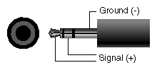 |
Table C-1 shows the port pinout information for the microphone.
Table C-1. Microphone Port Pinout
Microphone | Tip | Ring | Sleeve |
|---|---|---|---|
Silicon Graphics supplied electret mono microphone | Signal(+) | Signal(+) | Ground(-) |
Line level mono microphone | Ground (-) | Signal (+) | Ground (-) |
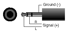 |
Above is the port and plug pinout for the speaker/headphone port.
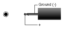 |
Above is the speaker power port and plug pinout.
Table C-3 shows the port pinout assignments for the speaker power port.
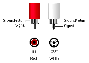 |
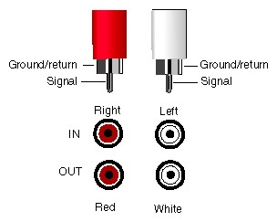
The port (jack) pinout for the coaxial digital ports and plugs are shown above.
Coaxial digital
Supports the AES3id professional format.
Compatible with consumer formats including CP340, IEC958, and S/PDIF.

Table C-4 shows the cable pinout assignments for the SCSI port.
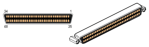 |
Pin | Assignment | Pin | Assignment |
|---|---|---|---|
1 | Ground | 35 | DB(12) |
2 | Ground | 36 | DB(13) |
3 | Ground | 37 | DB(14) |
4 | Ground | 38 | DB(15) |
5 | Ground | 39 | DB(P1) |
6 | Ground | 40 | DB(0) |
7 | Ground | 41 | DB(1) |
8 | Ground | 42 | DB(2) |
9 | Ground | 43 | DB(3) |
10 | Ground | 44 | DB(4) |
11 | Ground | 45 | DB(5) |
12 | Ground | 46 | DB(6) |
13 | Ground | 47 | DB(7) |
14 | Ground | 48 | DB(P) |
15 | Ground | 49 | Ground |
16 | Ground | 50 | Ground |
17 | Termpwr | 51 | Termpwr |
18 | Termpwr | 52 | Termpwr |
19 | Open | 53 | Open |
20 | Ground | 54 | Ground |
21 | Ground | 55 | ATN |
22 | Ground | 56 | Ground |
23 | Ground | 57 | BSY |
24 | Ground | 58 | ACK |
25 | Ground | 59 | RST |
26 | Ground | 60 | MSG |
27 | Ground | 61 | SEL |
28 | Ground | 62 | C/D |
29 | Ground | 63 | REQ |
30 | Ground | 64 | I/O |
31 | Ground | 65 | DB(8) |
32 | Ground | 66 | DB(9) |
33 | Ground | 67 | DB(10) |
34 | Ground | 68 | DB(11) |
 |
The Octane workstation autoselects the speed and type (duplex vs. half duplex) at bootup, based on what it is connected to.
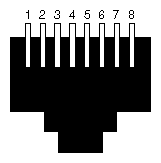
Table C-5 shows the cable pinout assignments for the Ethernet 10-Base-T/100-Base-T port.
Table C-5. Ethernet 10-BASE-T/100-BASE-T Port Pinout
Pin | Assignment |
|---|---|
1 | Transmit+ |
2 | Transmit– |
3 | Receive+ |
4 | (Reserved) |
5 | (Reserved) |
6 | Receive– |
7 | (Reserved) |
8 | (Reserved) |
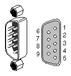
Table C-6 shows the cable pinout assignments for the IEEE 1284-C parallel port.
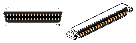 |
Table C-6. Parallel Port Pinout
Pin | Assignment | Pin | Assignment |
|---|---|---|---|
1 | BUSY | 19 | Signal Ground (BUSY) |
2 | SELECT | 20 | Signal Ground (SELECT) |
3 | nACK | 21 | Signal Ground (nACK) |
4 | nFAULT | 22 | Signal Ground (nFAULT) |
5 | pERROR | 23 | Signal Ground (pERROR) |
6 | DATA 1 | 24 | Signal Ground (DATA 1) |
7 | DATA 2 | 25 | Signal Ground (DATA 2) |
8 | DATA 3 | 26 | Signal Ground (DATA 3) |
9 | DATA 4 | 27 | Signal Ground (DATA 4) |
10 | DATA 5 | 28 | Signal Ground (DATA 5) |
11 | DATA 6 | 29 | Signal Ground (DATA 6) |
12 | DATA 7 | 30 | Signal Ground (DATA 7) |
13 | DATA 8 | 31 | Signal Ground (DATA 8) |
14 | nINIT | 32 | Signal Ground (nINIT) |
15 | nSTROBE | 33 | Signal Ground (nSTROBE) |
16 | nSELECTIN | 34 | Signal Ground (nSELECTIN) |
17 | nAUTOFD | 35 | Signal Ground (nAUTOFD) |
18 | HOST LOGIC HIGH | 36 view | PERIPHERAL LOGIC HIGH |
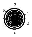 |
This is a standard pinout for PC PS/2 keyboards and mice. The mouse and keyboard are electrically PS/2 compatible. They also use the same protocol as the PC PS/2 keyboards and mice.
Table C-7 shows the cable pinout assignments for the keyboard and mouse ports.
Table C-7. Keyboard and Mouse Port Pinout
Pin | Assignment |
|---|---|
1 | Keyboard/Mouse Data |
2 | (Reserved) |
3 | Ground |
4 | Keyboard/Mouse Power (+5V) |
5 | Keyboard/Mouse Clock |
6 | (Reserved) |
The Octane workstation serial ports can operate in one of several modes:
RS-232 electrical levels with a standard PC pinout.
Macintosh style electrical levels and a Macintosh-compatible pinout. (This mode requires an additional adapter cable. See “Serial Port Adapter Cables”.)
ANSI/SMPTE 207M electrical levels and pinout. (This mode requires an additional adapter cable. See “Serial Port Adapter Cables”.)
This the PC-compatible pinout. The range of supported baud rates is 300 baud to 460K baud.
Table C-8 shows cable pinout assignments for the serial ports.
Table C-8. Serial Port Pinout - PC-Compatible
Pin | Assignment | Description |
|---|---|---|
1 | DCD | Data Carrier Detect |
2 | RD | Receive Data |
3 | TD | Transmit Data |
4 | DTR | Data Terminal Ready |
5 | SG | Signal Ground |
6 | DSR | Data Set Ready |
7 | RTS | Request to Send |
8 | CTS | Clear to Send |
9 | RI | Ring Indicator |
This is the Macintosh-compatible pinout.
Table C-9 shows cable pinout assignments for the serial ports.
Table C-9. Serial Port Pinout - Macintosh-Compatible
Pin | Assignment | Description |
|---|---|---|
1 | GPi | General Purpose Input |
2 | RxD- | Receive Data- |
3 | TxD- | Transmit Data - |
4 | TxD+ | Transmit Data + |
5 | SG | Signal Ground |
6 | RxD+ | Receive Data + |
7 | HSKo | Handshake Out |
8 | HSKi | Handshake In |
9 | Unused |
|
This section contains cable pinout information for serial cables that you can connect to your Octane workstation. It also describes Silicon Graphics serial port converters. The following topics are covered:
For serial printers and dumb terminals, use a 3-wire standard PC cable. Table C-10 shows the cable connector pinout assignments for this cable.
| Note: For a 3-wire cable and no hardware flow control modem, you must use the /dev/ttyd* command devices in the configuration files. For more detailed information, see the serial man page. To access the man page, from the Toolchest, choose Help > InfoSearch > Man pages. Or place the cursor in the console window and type |
man serial |
Table C-10. Printer/Dumb Terminal Cable Pinout
Signal Description | Pin Number | Pin Number |
|---|---|---|
| 1 | NOT CONNECTED |
RXD | 2 | 2 |
TXD | 3 | 3 |
| 4 | NOT CONNECTED |
GND | 5 | 7 |
| 6 | NOT CONNECTED |
| 7 | NOT CONNECTED |
| 8 | NOT CONNECTED |
| 9 | NOT CONNECTED |
Use a full-handshake (includes RTS and CTS) PC modem serial cable for a modem with RTS/CTS flow control. Table C-11 shows the cable connector pin assignments for this cable.
You can use this cable for all serial devices except those that do not need RTS flow control. Devices like serial printers and dumb terminals that do not need RTS flow control can still be used with this cable provided that a null modem adapter is added to one end of the cable. You can purchase the full-handshake PC modem serial cable from Silicon Graphics or your local service provider.
| Note: If you are attaching a modem with modem signals and RTS/CTS flow control, you must use the /dev/ttyf* command devices in the configuration files. For more detailed information, see the serial man page. To access this man page, from the Toolchest, choose Help > InfoSearch > Man pages. Or place the cursor in the console window and type |
man serial |
Table C-11. PC Modem Cable Pinout
Signal Description | Pin Number | Pin Number |
|---|---|---|
DCD | 1 | 8 |
RXD | 2 | 3 |
TXD | 3 | 2 |
DTR | 4 | 20 |
GND | 5 | 7 |
DSR | 6 | 6 |
RTS | 7 | 4 |
CTS | 8 | 5 |
RI | 9 | 22 |
The Octane workstation's serial ports conform to the PC standard pinout for EIA standard RS-232 signals.
The purpose of the adapter cable is to allow the Octane workstation to use standard PC or Macintosh serial devices.
Table C-12 shows the adapter cable pinout for a standard PC or Macintosh serial port.
Table C-12. Female DB9 to Female MiniDIN8 Adapter Cable Pinout
From Female DB9 | To MiniDIN8 | PC Signal | Macintosh Signal |
|---|---|---|---|
1 | 7 | DCD | GPi |
2 | 5 | RD | RxD- |
3 | 3 | TD | TxD- |
4 | 1 | DTR | TxD+ |
5 | 4 | SG | SG |
6 | 8 | DSR | RxD+ |
7 | 6 | RTS | HSKo |
8 | 2 | CTS | HSKi |
9 | unused | RI | unused |
The purpose of the following adapter cable is to support ANSI/SMPTE Standard 107M-1992.
Table C-13 shows the pinout for a female DB9 to female DB9 adapter cable.
Table C-13. Female DB9 to Female DB9 Adapter Cable Pinout
Female DB9 Connected to Octane | Female DB9 Connected to Peripheral |
|---|---|
1 | unused |
2 | to DB9 -2 (RxD-) |
3 | to DB9-8 (TxD-) |
4 | unused |
5 | to DB9-6and DB9-4 (GND) |
6 | to DB9-7 (RxD+) |
7 | to DB9-3 (TxD+) |
8 | unused |
9 | unused |
| Note: For more detailed information, see the serial man page. To access it, place the cursor in an IRIX shell and enter |
man serial |
Or, access Man Pages through the Toolchest > Help or in the InfoSearch window, enter
man serial |
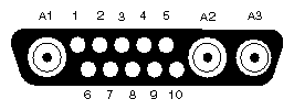 |
Table C-14 shows the port pinout assignments for the Octane 20 inch monitor. Table C-15 shows the port pinout assignments for an Octane DDC enabled monitor.
Table C-14. 20 Inch Monitor Pinout
Pin | Assignment |
|---|---|
A1 | Red Signal, Analog |
A2 | Green Signal, Analog |
A3 | Blue Signal, analog |
1 | Monitor ID Bit 3, TTL |
2 | Monitor ID Bit 0, TTL |
3 | Composite Sync (Active Low), TTL |
4 | Horizontal Drive (Active High), TTL |
5 | Vertical Drive (Active High), TTL |
6 | Monitor ID Bit 1, TTL |
7 | Monitor ID Bit 2, TTL |
8 | Ground |
9 | Ground |
10 | Ground |
Table C-15. DDC Enabled Monitor Pinout
Pin | Assignment - DDC Enabled |
|---|---|
A1 | Red |
A2 | Green |
A3 | Blue |
1 | Data Clock (SCL) |
2 | Bi-directional Data (SDA) |
3 | Composite Sync |
4 | Horizontal Sync |
5 | Vertical Sync |
6 | DDC (+5VInput) |
7 | DDC Ground |
8 | Chassis Ground |
9 | Chassis Ground |
10 | Chassis Ground |
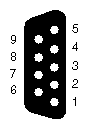 |
Table C-16 shows the cable pinout assignments for the StereoView port on the graphics boards.
Table C-16. StereoView Pinout Assignments
Pin | Assignment |
|---|---|
1 | Stereo left/right Eye Signal (1=left, 0=right) (STEREO_LEFT) |
2 | Signal Return Ground |
3 | Reserved for Future Use |
4 | Signal Return Ground (Framelock ground) |
5 | Reserved for Future Use (Framelock) |
6 | Digital Return Ground |
7 | Digital Return Ground for StereoView |
8 | +12V DC Output to StereoView Device |
9 | Unused |
Table C-17 shows the physical environent specifications for the Octane workstation.
Table C-17. Physical Environment Specifications
Workstation dimensions | 16.25” (41.3 cm) H x 11.0” (28 cm) W x 13.25” (33.7 cm) D 14.75” D (37.5 cm) (depth in localized area of power supply) 16.25” D (41.3 cm) (depth in localized area of optional PCI module) |
Power Requirements | Voltage and frequency: 100-240 VAC, 50-60 Hz, 10-4.2A, 850W |
Ambient Temperature | +13o C (23.4o F) to +35o C (95o F) (operating) -10o C (14o F) to +65o C (149o F) (non-operating) |
Relative Humidity | 10% to 80% operating (no condensation) 10% to 95% non-operating (no condensation) |
Heat Dissipation | 700 watts, 2400 Btu/hr |
Altitude | 10,000 ft. (3,049 m) operating; 40,000 ft. (12,195 m) non-operating |
Vibration | 0.02', 5-19Hz; 0.35 G, 19-500 Hz |
Voltage and frequency | 100-120/200-240 VAC |
Table C-18 shows microphone specifications.
Table C-18. Microphone Specifications
Microphone Jack |
|
|---|---|
Connector | 3.5 mm stereo mini |
Power | +5 V phantom power on tip |
Type | Unidirectional electret condenser |
Table C-19 shows speaker specifications.
Table C-19. Speaker Specifications
Speakers |
|
|---|---|
Rated power | 3 W(average) per channel |
Frequency range | 180 Hz - 15K Hz |
Magnetic flux leakage | <50 mGauss @2 cm |
Input impedance | 150 ohms |
Signal connector | 3.5 mm stereo mini |
Power connector | 2.5 mm mono micro |
Table C-20 shows headphone specifications.
Table C-20. Headphone Specifications
Headphones |
|
|---|---|
Recommended impedance | 35 ohms |
Connectors | 3.5 mm stereo mini |
Table C-21 provides Analog audio line level specifications
Table C-21. Analog Line Level Specifications
Specifications | Line In | Line Out |
|---|---|---|
Line level | -10dBV | -10dBV |
0dBFS Maximum | +10dBV to -22dBV | 6.5dBV ± 0.5dBV |
Total power for the PCI module (the sum of power for all boards from all power supply rails) must not exceed 45.0W (average 15.0W per board).
The Octane PCI module is a 5V system environment.
Table C-22. PCI Module Power Specifications
Power Supply Rail | Maximum Current | Maximum Power |
|---|---|---|
3.3V | 10.0A | 33.0W |
5.0V | 9.0A | 45.0W |
12.0V | 1.5A | 12.0W |
-12.0V | 0.3A | 3.6W |
| Note: For additional information see Section 4.3.4.1, in the chapter called “Power Requirements,” in the PCI Local Bus Specification, Rev. 2.1, June l995 (PCI Special Interest Group, Portland, OR). |