This chapter contains the following sections that describe how to set up and operate an SGI Origin 300 server:
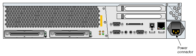
If you are operating your server on a table top, connect the server to a wall power receptacle. If your server resides in a rack, connect the server to a power distribution unit (PDU) or a power strip. Refer to Figure 3-1 for the location of the server's power connector.
This section explains how to attach and establish a connection between a system console and an SGI Origin 300 server. The system console enables you to perform the following activities:
Start an IRIX console session to set up networking and other configuration parameters.
Monitor your system by reading the status and error message information that the L1 controller generates.
Enter L1 controller commands to monitor or change particular system functions. You can, for example, monitor the speed of fans for a particular server. Refer to the SGI L1 and L2 Controller Software User's Guide (007-3938-00x) for descriptions of the L1 controller commands that you can use.
Power on or power off your server.
The system console can be a server that runs the SGIconsole remote multiserver management system or a personal computer (PC). SGIconsole provides a central server control environment that has the following features:
Support for SGI clusters, partitioned systems, and large single-system-image servers
Expandability to support additional servers
Rackmountable, space-efficient platform
Software applications and tools for installation and configuration, console functionality, and for monitoring and managing system-level performance
Web-based user interface
For instructions on how to attach a system console that runs SGIconsole software to your server, refer to the SGIconsole Hardware Connectivity Guide (007-4340-00x).
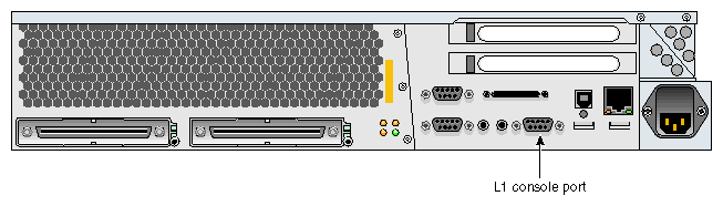
To attach a PC to your server, connect a null modem serial cable between the PC and the server's L1 console port (refer to Figure 3-2). Perform the following steps to establish a connection between your server and the system console (PC):
Ensure that the L1 controller of the server is powered on. When the server is connected to a power source, the L1 controller should be powered on.

Note: When powered on, the L1 controller displays “L1 running.” If it does not display “L1 running,” check the connection between the server and the power source. In addition, ensure that the circuit breaker of the power source is on. Power on the system console.
Ensure that the system console has the following network settings:
Baud 38400
No parity
8 data bits
1 stop bit
Hardware flow control on (RTS/CTS)
Type cu -l ttyd2 for an IRIX based console, or cu -l ttys0 -S38400 for a Linux based console, and then press Enter to display the L1 prompt. If the console uses another operating system, start a terminal emulation program as instructed in the console's user documentation.
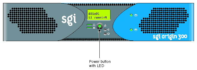
If your system does not have a system console, you can manually power on and off the server by using the power button that is located on the front of the Origin 300 server (refer to Figure 3-3).
Follow these steps to power on and boot your system using the system console:
Connect a console to the server system as described in “Connecting the System Console”.
For a system that contains one server, enter the following command at the L1 prompt to power on the server:
001c01-L1> power up
For a system that contains two servers or a server and a PCI expansion module, enter the following command at the L1 prompt to power on the server and the peer-attached server or PCI expansion module:
001c01-L1> * power up
Type Ctrl+D to view the power-on diagnostics (POD) and console output.
When POD is complete, the following menu appears:
System Maintenance Menu
1) Start System
2) Install System Software
3) Run Diagnostics
4) Recover System
5) Enter Command Monitor
Option?
Enter 1 to boot the system.
Follow these steps to power off your system using the system console.
| Caution: If you power off the system before you halt the operating system, you can lose data. |
Shut down the IRIX operating system by entering the following command:
# init 0
Type Ctrl+T to access the L1 prompt.
For a system that contains one server, enter the following command at the L1 prompt to power off the server:
001c01-L1> power down
For a system that contains two servers or a server and a PCI expansion module, enter the following command at the L1 prompt to power off the server and the peer-attached server or PCI expansion module:
001c01-L1> * power down
Before connecting two SGI Origin 300 servers, you must follow these steps to assign unique system ID numbers to the servers:
Designate one of the servers as the master server and the other server as the slave.
Connect a console to the slave server (refer to “Connecting the System Console”), and power on the server (refer to “Powering On and Off the Server”).
Use the brick slot <slotnumber> L1 command to set the slave system ID number to a higher number than the master system ID number. For example, if the master server's L1 prompt indicates that its ID number is 01 (001c01-L1>), then the slave system ID number should be 02 or higher (001c02-L1>).
001c01-L1>brick slot 02
brick slot set to 02.
Refer to the SGI L1 and L2 Controller Software User's Guide (007-3938-00x) for more information on L1 commands.
Follow these steps to connect two SGI Origin 300 servers with a NUMAlink 3 cable:
Power off both servers (refer to “Powering On and Off the Server”).
Connect the NUMAlink 3 cable to the LINK connectors on both servers.
Connect a system console to the master server, as described in “Connecting the System Console”.
Power on both servers as described in “Powering On and Off the Server”.
The console output should indicate that the processors and memory on both servers have been discovered. If the slave server has not been discovered, use the reset L1 command to perform a reset of the system.
| Note: For server-to-server communication to work correctly, the network mode on the server must be set to 422 (when connecting a PC [system console] to a serial port). Use the network L1 command to set the network mode. (Refer to the SGI L1 and L2 Controller Software User's Guide (007-3938-00x) for more information on L1 commands.) |
The front panel provides the following control features, as shown in Figure 3-4:
Status LEDs
Power button
Reset button
Non-maskable interrupt (NMI) button
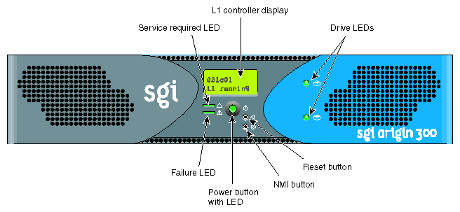
The front panel has the following LEDs:
Power button LED. Illuminates green when the internal components are on.
Service required LED. Illuminates yellow to indicate that an item is not functioning properly (for example, a fan is off), but the server is still operating.
Failure LED. Illuminates red to indicate that a failure has occurred and the server is down.
Press this button to power on the server. Alternatively, you can power on the server at a system console.
The L1 controller operates in one of the two following modes:
L1 Mode. The L1 prompt (001c01-L1>) is visible and all input is directed to the L1 command processor.
Console Mode from L1. Output from the system is visible and all input is directed to the system.
When you see a prompt of the following form, the L1 controller is ready to accept commands:
001c01-L1>
Refer to the SGI L1 and L2 Controller Software User's Guide (007-3938-00x) for a detailed list of L1 commands.
To enter console mode, press Ctrl+D at the L1 prompt, as follows:
001c01-L1> Ctrl+D entering console mode 001c01 console, <CTRL-T> to escape to L1 . <system output appears here> . |
To return to L1 mode, press Ctrl+T, as follows:
Ctrl+T escaping to L1 system controller 001c01-L1> |
At this point, you can enter any L1 command. When the command completes execution, the L1 returns to console mode:
re-entering console mode 001c01 console, <CTRL-T> to escape to L1 |
To permanently engage the L1 mode, press Ctrl+T and then enter the l1 command, as follows:
Ctrl+T escaping to L1 system controller 001c01-L1> l1 L1 command processor engaged, <CTRL-D> for console mode. 001c01-L1> |