This chapter describes the functional and physical components of the D-brick2 non-RAID mass storage option brick. It also explains how to power the D-brick2 on and off, and how to replace disk drive modules in the D-brick2. For troubleshooting and additional detailed information on the D-brick2, see SGI Total Performance 9100 (2Gb TP9100) Storage System User's Guide (P/N 007-4522-00x), which is available online at http://docs.sgi.com.
| Note: If you require RAID storage, ask your SGI sales representative about SGI RAID storage products, such as the SGI 2Gb TP9100 and SGI TP9500. |
This chapter is divided into the following five major sections:
For instructions on removing or replacing the drive carrier modules, see “Installing or Replacing a D-brick2 Drive Carrier Module” in Chapter 12.
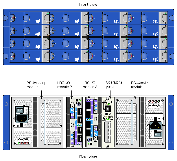
The optional D-brick2 module is a high performance, large-scale non-RAID storage system for your SGI rackmounted system. Each enclosure contains a minimum of 2 and maximum of 16 disk drives, and the component modules that handle I/O, power and cooling, and operations. Optional RAID storage systems are available for your system through your SGI sales representative. Figure 11-1 shows front and rear views of the D-brick2.
The modular design of the D-brick2 expands easily to meet your mass storage needs. This storage system provides compact, high-capacity JBOD ("just a bunch of disks") storage for supported SGI systems. Each D-brick2 is connected to one or more Fibre Channel boards (host bus adapters, or HBAs) in the SGI host system, either separately or in a combination (loop).
The optional D-brick2 storage system has the following features:
Maximum configuration of up to 96 drives (six D-brick2 units)
1x16 (more storage) and 2x8 (more bandwidth) disk topologies in each brick
Dual power feeds with dual power supplies
Redundant cooling
Non-disruptive component replacement
Enclosure services interface (ESI) for SCSI enclosure services (SES)
This section discusses the external D-brick2 components that you can access, add, replace, or upgrade. These include the following:
Drive carrier modules
Dummy” drive modules
Power supply and cooling modules
Operator's panel
Loop resiliency circuit (LRC) I/O modules
The first two items are accessed at the front of the module; the last three items are located in the rear of the D-brick2 unit.
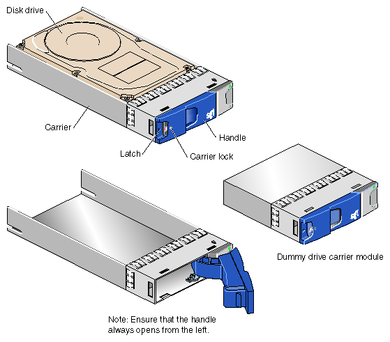
The disk drive carrier module consists of a hard disk drive mounted in a die-cast aluminum carrier (see Figure 11-2). The carrier protects the disk drive from radio frequency interference, electromagnetic induction, and physical damage. It also provides a means for thermal conduction.
Dummy drive carrier modules must be installed in all unused drive bays. They are designed as integral drive module front caps with handles and must be fitted to all unused drive bays to maintain a balanced airflow. Figure 11-2 shows examples.
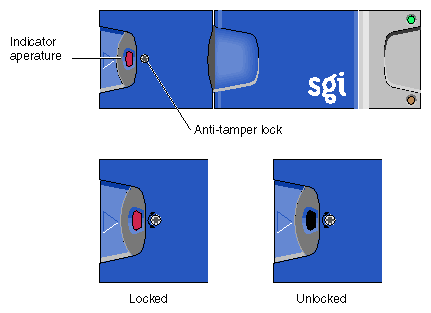
A key (Torx screwdriver) to lock or unlock the disk drives is provided with each D–brick2. A red indicator is visible in the center rectangular aperture in the handle if the anti-tamper lock is locked, and a black indicator is visible when the lock is unlocked (see Figure 11-3).
Two power supply/cooling modules (PSUs) are mounted in the rear of the D-brick2. These modules supply redundant cooling and power to the enclosure and are auto-ranging. The supplies should be plugged into your SGI rack's power distribution unit (PDU). Four LEDs mounted on the rear panel of the PSU/cooling module indicate the status of the power supply and the fans (see Figure 11-4).
| Note: If a power supply fails, do not remove it from the enclosure until you have a replacement power supply. The cooling fans in the supply will continue to operate. |
| Caution: You must finish replacing a PSU/cooling module within 10 minutes after removing one. Otherwise, thermal overload of the D-brick2 can result. |
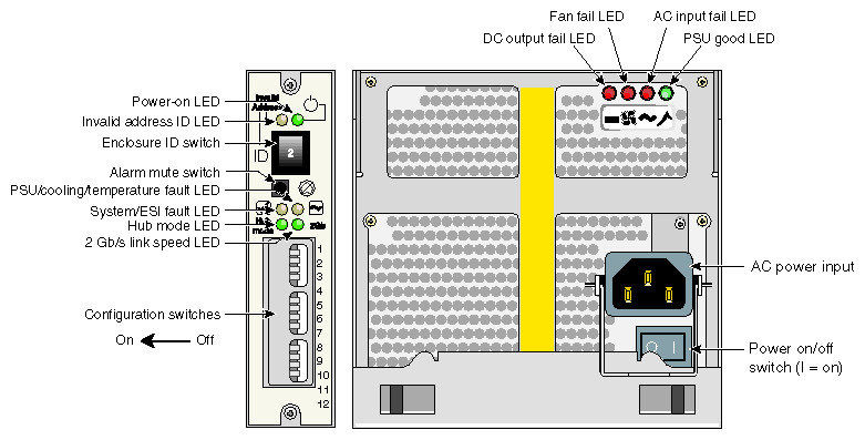
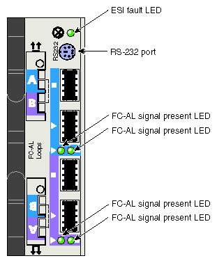
The operators panel (“ops panel”) contains an enclosure services processor that monitors and controls D-brick2 functions. The ops panel contains LEDs 9 show the status of all modules, an audible alarm that indicates a fault state is present, a push-button alarm mute switch, and a thumbwheel enclosure ID address range selector switch. When the D-brick2 is powered on, the audible alarm sounds for one second, and the power-on LED illuminates.
Figure 11-4 identifies all controls and indicators on the ops panel. Note that the operator's panel configuration switches slide left for “on” and right for “off.” For detailed descriptions of the LEDs and configuration switch information, see Chapter 5 in the SGI Total Performance 9100 (2Gb TP9100) Storage System User's Guide (P/N 007-4522-00x).
The D-brick2 uses a Fibre Channel arbitrated loop (FC-AL) to interface with the host computer system. The FC-AL backplane incorporates two independent loops formed by port bypass circuits within the LRC I/O modules. Figure 11-5 shows an LRC module.
Processors housed on the LRC modules provide enclosure management and interface to devices on the backplane, a PSU/cooling module, and an ops panel to monitor internal functions. These processors operate in a master/slave configuration to allow failover. See the SGI Total Performance 9100 (2Gb TP9100) Storage System User's Guide (P/N 007-4522-00x) for details.
| Note: The JBOD LRC I/O module can address up to 96 disk drives; a maximum of six enclosures can be cabled together. |
The enclosure may be configured with either one or two LRC I/O modules. If only one module is installed, an I/O blank module must be installed in the unused bay.
This section explains how to power the D-brick2 on and off.
Before powering on the D-brick2, confirm that the following is true:
Drives are seated in the correct bays and blank plates are fitted in any empty bays.
Ambient temperature is within the specified range of 10 ˚C to 40 ˚C (50 ˚F to 104 ˚F).
The system power distribution unit (PDU) is on.
To power on the D-brick2, follow these steps:
Connect an AC power cord to each PSU/cooling module.
Connect the AC power cords to the system PDU.
Turn the power switch on each PSU/cooling module to the “on” position (I = on, O = off). See Figure 11-4 for switch locations.
The green “PSU good” LED illuminates. Also, the “power on” LED on the ESI/ops panel (see Figure 11-4) of each module turns green when AC power is present.
If the “power on” LED on the ESI/ops panel does not illuminate, or if the amber “system/ESI fault” LED illuminates, verify that you followed all steps. For troubleshooting tips, see the SGI Total Performance 9100 (2Gb TP9100) Storage System User's Guide or contact your service provider.
Before powering off the D-brick2, confirm that the following has occurred:
All system users have been notified and are logged off.
Disk data has been backed up as appropriate.
To power off a D-brick2 enclosure, follow these steps:
Move the power switch on the rear of each PSU/cooling module to the “off” position (position I = on, O = off). See Figure 11-4 for switch locations.
Unplug the power cable from the PSU/cooling module(s) as appropriate. For example, you would follow this step
you are replacing a module.
If you are shutting down multiple bricks in the system, you may want to switch the PDU breaker switch to the “off” position.
The LEDs on the back of the unit should turn dark a few seconds after you power off the PSU/cooling module.
The rackmounted D-brick2 disk enclosure is 13.4 cm (5.3 in.) high, 50 cm (19.7 in.) deep, and 44.6 cm (17.5 in.) wide. Component weights, power requirements, and environmental information for the D-brick2 are provided in the following tables.
| Note: You should always follow system-level technical, operational, and environmental specifications, regardless of the tolerances of individual system bricks. |
Table 11-1 shows the weight s of the brick and the various D-brick2 components.
Table 11-1. D-brick2 Weight Information
Component | Weight |
|---|---|
D-brick2 enclosure, fully populated | 32.3 kg (71 lb) |
D-brick2 enclosure, empty | 17.9 kg (39.4 lb) |
Power supply/cooling module | 3.6 kg (7.9 lb) |
Disk carrier module with drive | 0.88 kg (1.9 lb) |
LRC I/O module | 1.2 kg (2.6 lb) |
Table 11-2 shows the power requirements and specifications of the D-brick2.]
Table 11-2. D-brick2 Enclosure Power Specifications
Specification | Value |
|---|---|
Voltage range for rack | 200-240 VAC |
Voltage range selection | Automatic |
Frequency | 50-60 Hz |
Power factor | >0.98 |
Maximum power consumption | 700 VA |
Typical power consumption | 400 VA or less |
Inrush current (25 °C [77 °F] cold-start 1 PSU) | 100 A maximum peak for 4 ms, 25 A thereafter at maximum voltage |
Harmonics | Meets EN61000-3-2 |
Power cord: Plug Socket |
250 V, 10 A IEC 320 C-14, 250 V, 15 A |
Table 11-3 provides temperature and humidity requirements for D-brick2 modules.]
Table 11-3. D-brick2 Ambient Temperature and Humidity Requirements
Factor | Temperature | Relative Humidity | Maximum Wet Bulb |
|---|---|---|---|
Operating temperature | 5 °C to 40 °C | 20% to 80% noncondensing | 23 °C |
Non-operating temperature | 0 °C to 50 °C | 8% to 80% noncondensing | 27 °C |
Storage temperature | 1 °C to 60 °C | 8% to 80% noncondensing | 29 °C |
Shipping temperature | -40 °C to +60 °C | 5% to 100% nonprecipitating | 29 °C |
Table 11-4 provides additional environmental specifications for D-brick2 units.
Table 11-4. Additional Environmental Requirements for D-brick2
Environmental Factor | Requirement |
|---|---|
Altitude, operating | 0 to 3047 m (0 to 10,000 ft) |
Altitude, non-operating | -305 to 12,192 m (-1000 to 40,000 ft) |
Shock, operating | Vertical axis 5 g peak 1/2 sine, 10 ms |
Shock, non-operating | 30 g 10 ms 1/2 sine |
Vibration, operating | 0.21 grms 5-500 Hz random |
Vibration, non-operating | 1.04 grms 2-200 Hz random |
Acoustics | Less than 6.0 B LwA operating at 20 °C |
Safety and approvals | CE, UL, cUL |
EMC | EN55022 (CISPR22-A), EN55024 (CISPR24), FCC-A |