Indy Power Supply Information
This page serves to document the SGI Indy PSU in detail. This article relies heavily on information from SGUG forum user "Elf" who made a post in 2019 about this. Due to internal disagreements within SGUG, Elf chose to give Raion permission to rehost the info on TechPubs.
Physical Specifications
TThe Indy power supply is a hefty unit weighing in at just under 2kg on average.
| System Dimensions | ||
|---|---|---|
| Length | Height | Width |
| 34 cm | 7.5cm | 10cm |
The unit takes a standard NEMA C13 power input and has a Molex Mini-Fit Jr. 20-pin header for primary power, with auxiliary functions on a 2x10 0.1in spacing pin connector.
Electrical Specifications
The power supply consumes 170W at 100-240V two-phase mains AC voltage (50 and 60hz compatible).
| Voltage Rail Ratings | |
|---|---|
| +3.3V | 7A |
| +5V | 25A |
| +5V standby | 0.02A |
| +12V | 4.5A |
| -12V | 0.75A |
Pinouts

Power is supplied on a 20-pin Molex Mini-Fit Jr. type connector, with the motherboard side being the male connector and the power supply side being female. The pin numbers are as per the mechanical drawing. The +5V standby is supplied when the power supply is connected to AC line power but has main power turned off. The purpose of it is to power on the PSU.
| Main Pinout | ||
|---|---|---|
| Pin # | Wire Color | Function |
| 1 | White | +3.3V |
| 2 | White | +3.3V |
| 3 | Red | +5V |
| 4 | Red | +5V |
| 5 | Red | +5V |
| 6 | Red | +5V |
| 7 | Red | +5V |
| 8 | Red | +5V |
| 9 | Green | +5V Standby |
| 10 | Light Blue | -12V |
| 11 | Black | 0V |
| 12 | Black | 0V |
| 13 | Black | 0V |
| 14 | Black | 0V |
| 15 | Black | 0V |
| 16 | Black | 0V |
| 17 | Yellow | +12V |
| 18 | Black | 0V |
| 19 | Black | 0V |
| 20 | Black | 0V |
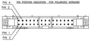
Auxiliary connections are supplied on a 20 position 0.1" spacing (2x10) pin header, with the motherboard side being male and the power supply side being female. Noting the position of the connector key, pin numbering on these connectors alternates between the bottom and top row, starting from the bottom left.
The power supply is controlled by pin 3 (Run), which is "ground to stop." It naturally floats at +5V (standby), meaning that disconnected from the motherboard, the power supply runs and supplies regular power. The motherboard grounds out this pin to stop the power supply.

| Pin Header Pinout for Indy | ||
|---|---|---|
| Pin # | Wire Color | Function |
| 1 | N/C | |
| 2 | Brown | Temperature Sensor Control Voltage (0-5V) |
| 3 | Red / White | Run (Ground to stop) |
| 4 | Orange | Power good signal |
| 5 | N/C | |
| 6 | N/C | |
| 7 | N/C | |
| 8 | N/C | |
| 9 | Gray | Power switch (other leg to Switch Common) |
| 10 | White | Volume Up switch (other leg to Switch Common) |
| 11 | Blue / White | Volume Down switch (other leg to Switch Common) |
| 12 | Periwinkle | Reset switch (other leg to Switch Common) |
| 13 | Black | Switch Common |
| 14 | Red | LED Common (Anode) |
| 15 | Violet | Red Status LED (Cathode) |
| 16 | Violet / White | Green Status LED (Cathode) |
| 17 | Orange / White | Speaker (terminal 1) |
| 18 | Green / White | Speaker (terminal 2) |
| 19 | N/C | |
| 20 | N/C | |
Sony vs Nidec
The debate in the community over which style of PSU is better is summarized as:
- Nidec - An electrically noisy, extremely inefficient PSU that keeps the Indy cool, or...
- Sony - A slightly more efficient, less noisy PSU that will cook the machine.
The difference between the Nidec and Sony fan control inside the power supply (both of which receive the same control signal voltage from the motherboard) is quite substantial.
The Nidec acts linearly, with the fan spinning slowly even at 0V of control signal (60F, 15.5C) and ramping up to maximum speed at 5V of control signal (180F, 82.5C) which puts the fan at 11.87V maximum.
The Sony does not act linearly, with a 3rd order polynomial fit. The voltage output by the Sony fan controller does not allow it enough torque to start spinning at all -- and only minimally -- until 2.17V of control signal, or in other words 113.1F / 45C in the vicinity of the CPU! It will need to be much hotter than that (e.g. 145F / 62.8C) before the fan really starts to blow. Interestingly the Sony fan has a higher maximum voltage, with a 5V control signal topping out at 15.76V to the fan, which at that point is going pretty fast.
This appears to be a design defect based on the information provided.