This chapter tells you how to install or remove a second hard disk drive in your O2+ workstation and how to connect external peripherals. The following topics are covered:
After you have installed the second hard disk, see “Setting Up a New Hard Disk” in the online Personal System Administration Guide for information on how to manage your disk space.
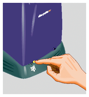
Turn off the workstation by pressing the power button on the front (Figure 3-1).
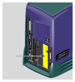
Locate the optional drive bay (Figure 3-2) where you will install the second internal hard drive. The drive bay is covered with a blank panel that you must remove.
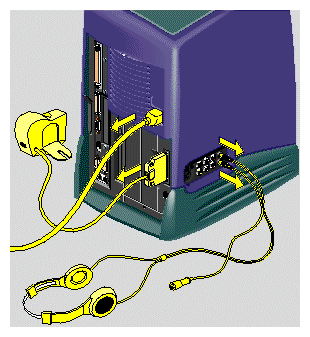
To remove the panel over the optional drive bay, you must first remove the audio-visual module located on the far right as you face the rear of the workstation. First, remove the power cable from the rear and any audio-visual cables that are connected to the side panel (Figure 3-3).
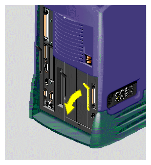
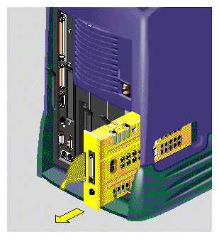
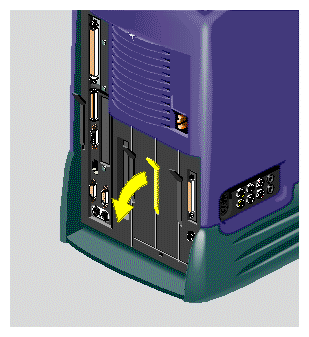
Release the audio-visual module by pulling down the lever (Figure 3-4).
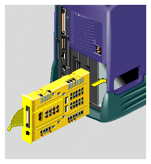
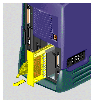
Slide the audio-visual module out of the chassis and place it carefully on a clean, flat, antistatic surface, such as your desktop (Figure 3-5).
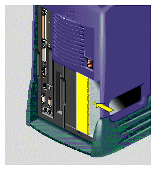
With your fingers, pry off the front panel that covers the optional drive bay (Figure 3-6).
Save the panel. If you remove the second drive and do not replace it, you must reinstall the panel.
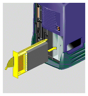
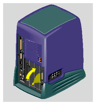
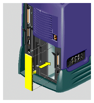
Slide the second hard drive into the optional drive bay until the lever engages (Figure 3-7).

Note: You do not need to set the SCSI address on the second drive. The optional drive bay on the O2+ workstation is preconfigured. Push the lever up to lock the drive module in place (Figure 3-8).
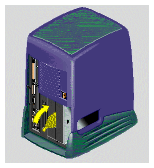
Slide the audio-visual module back into the bay on the far right of the chassis (Figure 3-9).
Push the lever up to lock the audio-visual module in place (Figure 3-10).
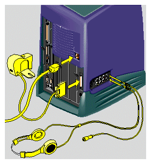
Reconnect the power cable to the rear of the workstation. Reconnect any audio and video cables that you removed from the side panel of the workstation (Figure 3-11).
Turn on the workstation by pressing the power button on the front (Figure 3-12).
To check that the system recognizes the new hard disk drive, from the Toolchest select System > System Manager > Hardware and Devices > Disk Manager. The system disk and the second disk are displayed.
For information on how to manage your disk space , see “Setting Up a New Hard Disk” in the online Personal System Administration Guide.
Before removing the second drive, read “Remove a Disk from the System” in the online Personal System Administration Guide to find out how to unmount the filesystem(s) on the drive you are removing.
| Note: If you do not unmount the necessary filesystem(s) before removing the disk, you will not compromise any data, but your system may start more slowly as it spends time looking for missing filesystems. |
Turn off the workstation by pressing the power button on the front (Figure 3-13).
Remove the power cable from the rear.
The second hard disk is in the optional drive bay—the one between the system drive and the audio-visual module. (The R12000class O2+ does not have an optional drive bay.) Pull down the lever on the left side of the optional drive module to release it (Figure 3-14).
Pull the drive module out of the chassis (Figure 3-15).
If you are installing another optional hard drive, see steps 7 and 8 of “Installing a Second Internal Hard Drive in an RM7000class Workstation”. Otherwise, replace the blank filler panel over the open drive slot (Figure 3-16). (You removed the panel when you first installed the drive.)
Reconnect the power cable to the rear of the workstation (Figure 3-17). Reconnect any audio-visual cables that you removed from the side or rear panel of the workstation.
The following information is covered in this section:
You can connect one or more external SCSI devices in a daisy-chain to the O2+ single-ended, wide SCSI bus if the maximum combined cable length of all external SCSI cables does not exceed three meters. You can connect either 16-bit wide (68-pin) or 8-bit narrow (50-pin) SCSI devices, but you should follow the guidelines about where to place the devices on the chain, in “Connecting More Than One External SCSI Device”.
Each device has a unique SCSI address and is connected to the other devices in a chain, with the first device connected to the SCSI port on the rear of the workstation. The last device on the daisy-chain must be terminated with an active SCSI terminator .
| Caution: For external SCSI devices to operate reliably, the maximum combined cable length of all external SCSI cables cannot exceed three meters. Use the cable and active SCSI terminator that came with the device. If you are using other types of cables or terminators, data loss can result. |
External SCSI devices include the following drives: 1/4-inch cartridge tape, digital audio tape, digital linear tape, optical disk, removable cartridge disk, and hard disk. SCSI scanners are also supported.
Each device on the daisy-chain needs a unique numeric SCSI address to distinguish it from other devices. The O2+ workstation has two built-in SCSI buses. The system drive, the optional hard drive (if installed), and the internal CD-ROM drive are on the internal SCSI bus.
All external devices are on the external SCSI bus. You can connect as many as 15 wide external devices or 7 narrow external devices, as long as the cable length limitation is not exceeded.
If you have one or more external devices connected to your system, and you want to add another device, check which addresses are assigned to the existing devices and then choose another number. Follow these steps:
From the Toolchest, select System > System Manager > About This System.
Pick an unassigned number between 1 and 15 for the device that you are adding.
If the SCSI devices and their addresses do not appear under “About This System,” type hinv in a shell window.
Now that you have chosen a SCSI address, you need to set the address manually on the device that you will install. Most SCSI devices have a push-button switch or dial. The switch or dial is usually located on the rear or bottom of the device. You may need a small screwdriver or pen tip to set the dial or push the buttons. See the following:
If you will install the first external SCSI device, see “Connecting One External SCSI Device”.
If you will install additional SCSI devices, see “Connecting More Than One External SCSI Device”.
To connect one external SCSI device, follow these steps:
Turn off the workstation (Figure 3-18).
Choose the appropriate cable, as follows:
For a SCSI device with a wide 68-pin connector, use a 68-pin SCSI-3 to 68-pin SCSI-3 cable (0.75 meter).
For a SCSI device with a narrow 50-pin connector, use a 68-pin SCSI-3 to 50-pin Centronics SCSI-2 cable (0.75 meter).
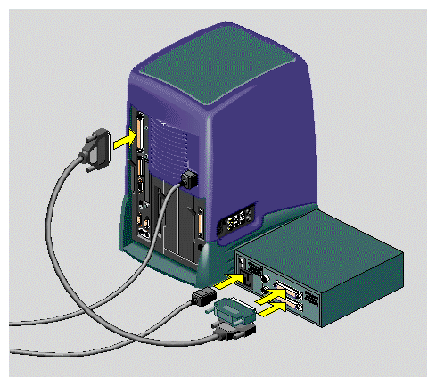
Connect the SCSI cable to the SCSI port on the rear of the workstation and to the SCSI connector on the back of the device. If there are thumbscrews on either side of the connectors, tighten them (Figure 3-19).
Note: The illustration shows an RM7000class workstation. The process of connecting an external SCSI device is the same on an R12000class workstation. Connect the power cable to the SCSI device and to a working electrical outlet.
Connect the active SCSI terminator to the device.
Turn on the device, and then turn on the workstation. You must turn on the equipment in this order, so that the workstation recognizes the device.
To check that the system recognizes the new SCSI device, from the Toolchest, select System > System Manager > About This System. External SCSI devices are shown here.
For more information, see “Hardware and Devices” in Personal System Administration Guide.
Read the following guidelines before you begin the process of connecting the SCSI device.
You can connect both 16-bit wide (68-pin) and 8-bit narrow (50-pin) SCSI devices to the workstation, but you must install the wide devices as a group closest to the workstation. Place the narrow devices at the end of the daisy-chain.
If the first external device is a 68-pin device, you can daisy-chain a 50-pin device to it, but you cannot then daisy-chain a 68-pin device to the 50-pin device.
You can use a 68-pin device as the first device, a 68-pin device as the second device, and a 50-pin device as the third device.
On an O2+ workstation, wide and narrow SCSI devices can coexist on the same bus because the SGI 68-pin to 50-pin cable includes an active terminator for the extra data lines in the 68-pin connector.
In summary, the accepted and incorrect configurations are as follows:
Accepted configurations:
68-pin to 50-pin
68-pin to 68-pin to 50-pin
Incorrect configuration:
68-pin to 50-pin to 68-pin
To connect more that one external SCSI device, follow these steps:
Turn off the workstation (Figure 3-20).
Read the instructions in “Choosing a SCSI Address for the External Device” and “Setting the SCSI Address on the External Device”. Then return here.
Remove the active SCSI terminator from the first device on the daisy-chain.
Choose the appropriate SCSI cable , as follows:
For the first external device, choose as follows:
For the SCSI device with a wide 68-pin connector, use a 68-pin SCSI-3 to 68-pin SCSI-3 cable (0.75 meter).
For the SCSI device with a narrow 50-pin connector, use a 68-pin SCSI-3 to 50-pin Centronics SCSI-2 cable (0.75 meter).
For the second and all other devices on the daisy-chain, choose as follows:
For the SCSI device with a wide 68-pin connector, use a 68-pin SCSI-3 to 68-pin SCSI-3 cable (0.25 meter).
For the SCSI device with a narrow 50-pin connector, use a 50-pin Centronics SCSI-2 to 50-pin Centronics SCSI-2 cable (.5 meter).
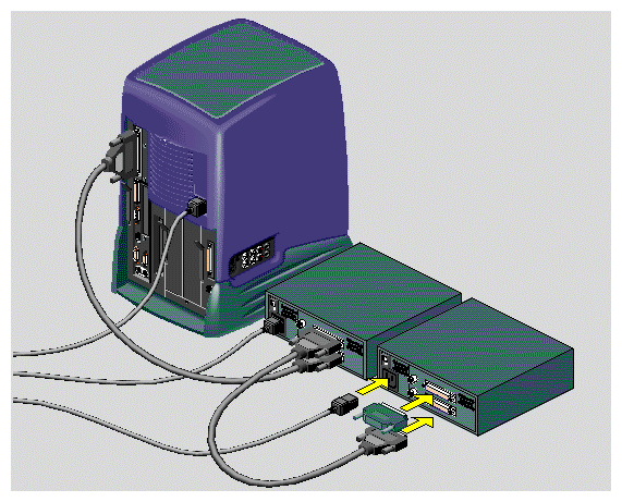
Link the devices in a daisy-chain (Figure 3-21), as follows:
First device: Connect the SCSI cable to the device and to the workstation. If there are thumbscrews on either side of the connectors, tighten them.
Second and all other devices: Connect the SCSI cable to the connector on the back of each device. If there are thumbscrews on either side of the connectors, tighten them.
Note: The illustration shows an RM7000class workstation. The process of connecting external SCSI devices is the same on an R12000class workstation. Connect a power cable to each SCSI device and to a working electrical outlet.
Connect the active SCSI terminator to only the last device on the daisy-chain.
Turn on each device, and then turn on the workstation. You must turn on the devices in this order, so that the workstation recognizes the devices.
To check that the system recognizes the new SCSI devices, from the Toolchest select System > System Manager > About This System. External SCSI devices are shown here.
For more information, see “Hardware and Devices” in the Personal System Administration Guide.
Examples of serial devices you can connect to your O2+ workstation include: dial and button boxes , digitizer tablets , console terminals , modems , optical mice, MIDI (Musical Instrument Digital Interface) devices, Spaceball, and the Logitech Magellan 3D input device.
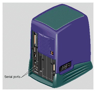
Figure 3-22 shows the location of the serial ports on the rear of the workstation. The serial ports are labeled 1 and 2 and are DB9 connectors. To view the serial port cable pinouts, and for information on Silicon Graphics serial cables and converters, see Hardware Central . (If your Web browser is not loaded, it takes a few seconds to load.) Or, if you are viewing this on a remote server, see Appendix A, “Technical Specifications”.
| Note: The illustration shows an RM7000class workstation. The process of connecting serial devices is the same on an R12000class workstation. |
Before connecting the device, use the Serial Device Manager to configure the serial port you will use. From the Toolchest select System > System Manager > Hardware and Devices > Serial Devices Manager.
Connect one end of the serial cable to the serial port (Figure 3-22). Connect the other end to the serial device, as follows:
If connecting a console terminal, attach it to serial connector 1 only.
If connecting a dial and button box, you need to attach a female-to-female adapter to the serial cable before connecting it to the workstation.
If connecting a Macintosh compatible MIDI (Musical Instrument Digital Interface) equipment, you need the Silicon Graphics MIDI converter. To purchase one, contact your Silicon Graphics service provider.
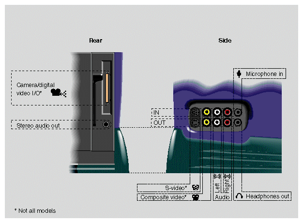
Figure 3-23 shows the location of the audio and video ports on the workstation.
| Note: The illustration shows an RM7000class workstation. The process of connecting audio and video devices is the same on an R12000class workstation. |
For cable pinout information, see Hardware Central . (If your Web browser is not loaded, it takes a few seconds to load.) Or, if you are viewing this on a remote server, see “Cable Pinout Assignments” in Appendix A.
For information on digital audio and video tools, see Digital Media Tools User's Guide , or in the Help menus of digital media applications.
The side panel audio ports support:
Stereo line level in and out (RCA plugs)
Stereo headphone out (3.5 mm phono)
Mono microphone in (3.5 mm phono)
The rear panel audio ports support:
Stereo line out (3.5-mm phono)
Embedded microphone in the O2Cam
| Note: The video option is not available on all models. |
Your workstation can send and receive analog composite video (RCA) and S-video (MiniDIN) signals. In addition, the digital camera port provides a digital video input and output signal. The signal is proprietary to SGI and is similar to the parallel D-1 signal used in professional video applications.
The analog S-video and analog composite video ports accept most consumer and industrial-grade video equipment.
For cable pinout information, see Hardware Central . (If your Web browser is not loaded, it takes a few seconds to load.) Or, if you are viewing this on a remote server, see “Cable Pinout Assignments” in Appendix A.
| Note: Connect the O2Cam before turning on the workstation, so that the system recognizes the camera. |