This chapter provides safety information and instructions for adding or removing components from your Silicon Graphics® Tezro™ visual workstation. These topics are covered in the following sections:
“Replacing Enclosure Components”

Caution: For your own safety and to avoid damage to your equipment, do not attempt to install or remove components that are not listed in this chapter.
Read and follow these instructions carefully before servicing your workstation.
Follow all warnings and instructions marked on the system and noted in this and other documentation included with this system.
Unplug the system from the wall outlet before cleaning. Do not use liquid cleaners or aerosol cleaners. Use a damp cloth for cleaning.
Do not use the workstation near water.
Do not place the system on an unstable cart, stand, or table. It may fall, causing serious damage to the system.
Slots and openings on the workstation are provided for ventilation. To ensure reliable operation of the system and to protect it from overheating, these openings must not be blocked or covered. This system should never be placed near or over a radiator or heat register, or in a built-in installation, unless proper ventilation is provided.
This system should be operated from the type of power indicated on the marking label. If you are not sure of the type of power available, consult your dealer or local power company.
Do not allow anything to rest on the power cord. Do not locate this system where people will walk on the cord.
Never push objects of any kind into this system through cabinet slots as they may touch dangerous voltage points or short out parts, which could result in a fire or electric shock. Never spill liquid of any kind on the system.
Do not attempt to service this system yourself except as noted in this guide. Opening or removing covers of node and switch internal components may expose you to dangerous voltage points or other risks. Refer all servicing to qualified service personnel.
Unplug this system from the wall outlet and refer servicing to qualified service personnel under the following conditions:
When the power cord or plug is damaged or frayed.
If liquid has been spilled into the system.
If the system has been exposed to rain or water.
If the system does not operate normally when the operating instructions are followed. Adjust only those controls that are covered by the operating instructions since improper adjustment of other controls may result in damage and will often require extensive work by a qualified technician to restore the system to normal condition.
If the system has been dropped or the cabinet has been damaged.
If the system exhibits a distinct change in performance, indicating a need for service.
Use only the proper type of power supply cord set (provided with the system) for this unit.
Only qualified service personnel should replace the soldered lithium battery(s) in the workstation. Please see “Lithium Battery Compliance Statement” in Appendix B for more information.
Replacement parts are available directly from your local service provider. Contact the SGI support office for more information.
All of the procedures in this chapter can be performed with the following tools:
Wrist grounding strap
T15 Torx driver
Small flat-blade screwdriver
Small phillips-blade screwdriver
This section shows you how to open the workstation for service and protect the components from static damage. The following topics are covered:
Follow these steps to power off and remove cables from your workstation:
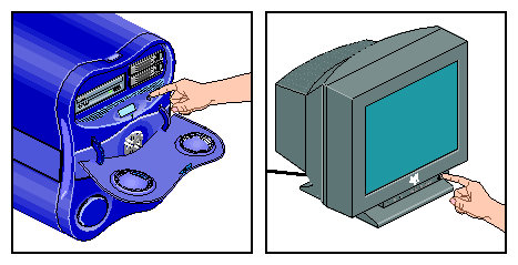
If you are logged in to the workstation, log out. Then, press the power buttons to power off your workstation and monitor (see Figure 3-1).
Disconnect all of the cables from the rear of the workstation. Be sure to note where each cable is connected, so that you can reconnect them correctly when you have finished servicing the system.

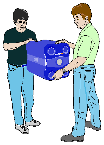
Note: You do not need to disconnect the cables or move the workstation for some procedures. Refer to the individual procedures for detailed instructions on preparing the system. Move the workstation to a sturdy, flat surface. Always use two people to move the workstation (see Figure 3-2).
This section shows you how to open the enclosure in the following sections.
To determine which side(s) of the enclosure you need to remove to access specific components, see Table 3-1. If a part appears in two columns, you must remove both panels in order to access that component.
Table 3-1. Component Access by Enclosure Panel
Right Side Panel | Left Side Panel | Front Side Panel (Bezel) |
|---|---|---|
Memory DIMMS Hard Disk Drive Fan Rear Fan Assembly | IO9 board XIO boards L1 display cable LED cable PCI boards DVD-ROM drive Fan wall | L1 display L1 display cable LED cable
|
After you have determined which side(s) of the enclosure you need to open, proceed to the appropriate section.
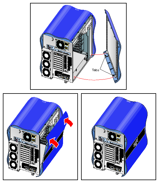
Follow these steps to open the left or right side of the enclosure:
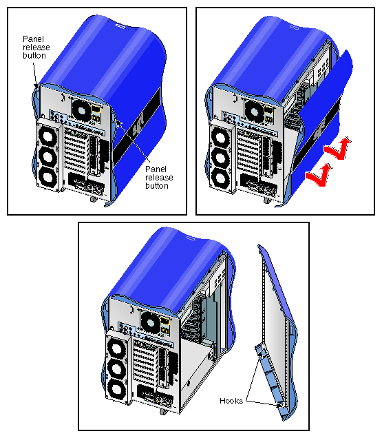
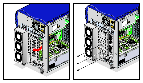
Press the panel release button on the rear of the enclosure. Then swing the top edge of the panel away from the enclosure (see Figure 3-3).
Lift the panel until the hooks on the bottom edge clear the lip on the base of the enclosure. Then swing the bottom edge of the panel away from the enclosure and place it in a safe location (see Figure 3-3).
If you only need to remove the left or right side panel, proceed to “Installing or Removing Internal Parts”. If you need to remove the bezel of the workstation, proceed to the next section.
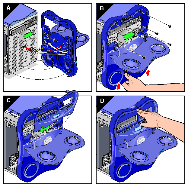
The front of the enclosure is covered by a decorative plastic bezel. The bezel is made up of two pieces: the bezel frame and the drive shroud. The bezel frame covers the front of the enclosure. The drive shroud mounts inside the bezel frame and covers the area adjacent to the DVD-ROM drive and hard disk drives.
Follow these steps to remove the bezel from the front of the enclosure:
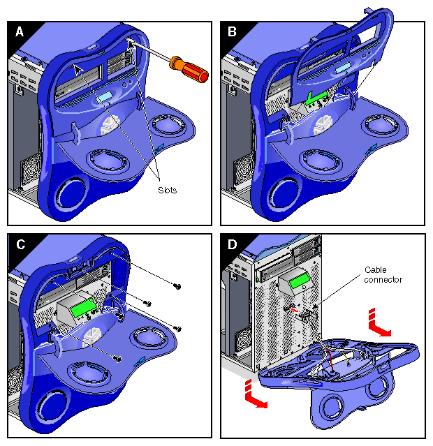
Open the door on the front of the bezel.Use a small flat-bladed screwdriver to press down in the two slots at the top of the drive shroud.
Tilt the top of the drive shroud toward you. Then lift the shroud off of the three tabs that are supporting it and place it in a secure location.
Remove the five screws that were covered by the drive shroud. Place these screws in a secure location.
Tilt the top of the bezel frame toward you. Then reach behind the bezel frame and disconnect the LED cable by squeezing the spring clips on the LED cable connector and gently pulling. Lift the bezel off of the enclosure and place it in a secure location.
Proceed to the next section to install or remove internal components.
| Warning: The heat sinks on the interface board get very hot. Wait 5 minutes after powering off your workstation before you touch any internal components. Touching the heat sinks could result in burns if a cooling-off period is not observed. |
Unroll the first two folds of the strap.
Wrap the exposed adhesive side firmly around your wrist, unroll the rest of the strap, and then peel the liner from the copper foil at the opposite end.
Attach the copper foil to an exposed electrical ground, such as a metal part of the chassis.
After you attach the wrist strap, you can install or remove internal parts of the workstation. Table 3-2 contains a list of all of the internal components that you can install or remove and the procedure associated with each one.
| Caution: Do not attempt to install or remove components that are not listed in Table 3-2. Components not listed in Table 3-2 must be installed or removed by a qualified SGI field engineer. |
Table 3-2. C ustomer-replaceable Components and Service Procedures
Component | Procedure |
|---|---|
Memory DIMMs | “Installing or Removing a Memory DIMM”
|
Internal hard disk drives | “Installing or Removing Internal Hard Disk Drives”
|
DVD-ROM Drive | “Installing or Removing the DVD-ROM Drive ”
|
PCI and XIO Boards: IO9 board XIO boards PCI boards |
“Installing or Removing XIO Boards”
“Installing or Removing PCI Boards”
|
Fans: Fan wall Hard disk drive fan Rear fan assembly |
“Replacing the Hard Disk Drive Fan ”
“Replacing the Rear Fan Assembly ”
|
Internal Cables: L1 display cable LED cable DVD-ROM drive cable |
“Replacing the L1 Display Cable ”
“Replacing the DVD-ROM Drive Cable”
|
Enclosure Components: Enclosure Bezel Assembly Enclosure Side Plastics Enclosure Top Plastics L1 Controller Display |
“Replacing the Bezel Assembly”
|
When you are finished installing or removing internal components, proceed to the next section.
The following sections contain instructions for returning the workstation to service:
Follow these instructions to install the bezel.
Align the tabs on the lower portion of the bezel with the holes in the enclosure. Insert the tabs into the holes and press the bezel against the enclosure to ensure that it is properly seated.
Lift the bezel slightly to align the screw holes with the mounting holes in the enclosure. Then install the five screws that secure the bezel to the enclosure.
Align the three tabs on the lower edge of the drive shroud with the corresponding holes on the face of the enclosure. Then swing upper edge of the drive shroud toward the enclosure and press the two tabs on the upper edge into their holes. Press the shroud against the enclosure to ensure that it is properly seated.
Follow these steps to install a side panel (see Figure 3-6):
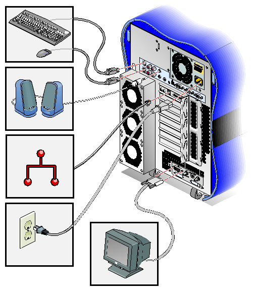
Follow these steps to cable and power on the workstation.
Reconnect all of the system cables to the rear of the enclosure (see Figure 3-7).
Press the power buttons on your workstation and monitor.
If your workstation does not boot correctly, see Chapter 4, “Troubleshooting and Diagnostics”.
This completes the procedure for returning the workstation to service.
The Silicon Graphics® Tezro™ visual workstation is configured with a minimum of 512 MB of memory and a maximum of 8 GB of memory. The memory is contained in dual in-line memory modules (DIMMs) which are installed in eight DIMM sockets on the system node board. The sockets are divided into four DIMM pairs. The instructions in the following sections assume that you know the correct slots in which to install the memory DIMMs. For information about DIMM configurations and placement rules, refer to “Memory DIMMs” in Chapter 2.
| Note: If you have not already done so, remove the right side of the enclosure to access the DIMMS. Refer to “Preparing the Workstation for Service”. |
Instructions are provided in the following sections:
To remove a DIMM, follow these steps:
Locate the DIMM that you want to remove.
Pull up on the latches at the end of the DIMM socket (see Figure 3-8). The DIMM will partially eject from the socket.
Lift the DIMM up and out of the enclosure.
Place the DIMM in an antistatic bag and store it in a secure location.
Note: Both sockets in a DIMM bank must be either empty or populated. If you remove one DIMM and do not plan to replace it immediately, also remove the other DIMM in the bank and replace it when you install a new DIMM. Install a new DIMM or return the system to service, as follows:
To replace the DIMM immediately, proceed to the next section, “Installing a DIMM”.
To return the system to service, see “Returning the Workstation to Service”.
Note: The workstation will not function if there are no memory DIMMs installed. Two memory DIMMs of equal size must be installed in DIMM pair number 1.
To install a DIMM, follow these steps:
| Caution: DIMMs are sensitive to static electricity. Be sure to wear the anti-static wrist strap while you complete these steps. |
Rotate the ejector latches on each end of the socket so that they stick straight out, as shown in Figure 3-9.
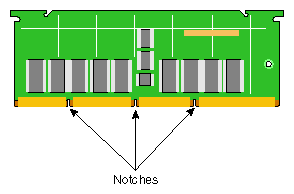
Align the DIMM with the socket. Make sure that the notches on the bottom of the DIMM align with the protrusions in the bottom of the socket (see Figure 3-10).
Seat the DIMM in the socket and press down. If you have seated the DIMM correctly, the ejector latches will swing up and click into place in the notches on the ends of the DIMM.
If necessary, repeat steps 1 through 3 to install a second DIMM.
Ensure that both sockets in the DIMM bank are full. DIMMs must be installed in pairs.
This completes the memory DIMM installation. To return the workstation to service, see “Returning the Workstation to Service”. After you have returned the system to service, you may verify that the memory you installed is working correctly by following the steps in the next section.
To verify the memory installation, follow these steps:
After you power on the system, select System Manager > Hardware and Devices > About This System from the Toolchest and check the amount of memory displayed for Main Memory. The displayed memory should equal the original amount of memory minus any memory you removed, plus the amount of memory you installed.
If the amount of memory is incorrect, power off the system and check the following:
Check the angle of the DIMMs. They should be upright and completely seated.
Ensure that each bank is populated with two DIMMs, and that they are the same size. You must have an even number of DIMMs installed.
The Silicon Graphics Tezro visual workstation can have one or two internal hard disk drives. These drives are sled mounted and can easily be installed and removed. The following sections contain instructions for installing and removing hard disk drives:
“Removing an Internal Hard Disk Drive ”
Note: You do not need to prepare the system for service to install or remove hard disk drives. If you are replacing the drive in the upper bay, ensure that it is spun down before you remove it. If you are replacing the system disk in the lower drive bay, you must power down the system.
To install a disk drive, follow these steps:
Open the bezel door. If there is an empty drive sled in the drive bay, remove it. To remove the drive sled, press in on the right side of the locking handle; the handle will unlatch from the enclosure. Swing the handle all the way open; then slide the drive sled out of the enclosure.
Move the handle on the drive you are installing to the fully open position. Then position the drive sled so that it engages the drive bay guide rails (see Figure 3-11).
Note: If there is only one disk drive in your system, it must be located in the lower drive bay. Gently push the drive sled into the drive bay until the locking handle engages with left side of the bay opening. Then swing the locking handle towards the enclosure until it latches (see Figure 3-11).
Open the bezel door.
Note: If you are removing the drive in the upper drive bay, ensure that the drive has spun down before you remove it. If you are removing the drive in the lower drive bay, you must power down the workstation. Press in on the right side of the locking handle; the handle will unlatch from the enclosure (see Figure 3-11).
Swing the locking handle away from the enclosure until it is fully open. Then carefully slide the drive sled out of the drive bay. Do not pull the drive sled out by the locking handle (see Figure 3-11).
If you are not installing a replacement drive, install an empty drive sled to ensure proper airflow.
The Silicon Graphics Tezro visual workstation supports an internal DVD-ROM drive which is installed in the 5.25-in. drive bay. This drive bay is located on the upper left portion of the front of the enclosure. The following sections contain instructions for installing and removing the DVD-ROM drive:
-
Note: If you have not already done so, prepare your system for service. Refer to “Preparing the Workstation for Service”. In order to install or remove the DVD-ROM drive, you must remove the left side panel and the drive shroud. You do not need to remove the entire bezel.
Follow these steps to install the DVD-ROM drive:
| Note: You must remove the drive shroud before you can install the DVD-ROM drive. |
Remove the plastic drive blanking plate that covers the DVD-ROM drive opening in the drive shroud. Then remove the metal blanking plate that covers the front of the DVD-ROM drive cage.
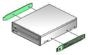
Attach the 5.25-in. drive rails to the sides of the drive by inserting the pins into the openings in the sides of the drive (see Figure 3-13).
Align the drive rails with the slots in the side of the drive cage and slide the drive into the drive cage until it clicks into place (see Figure 3-14).
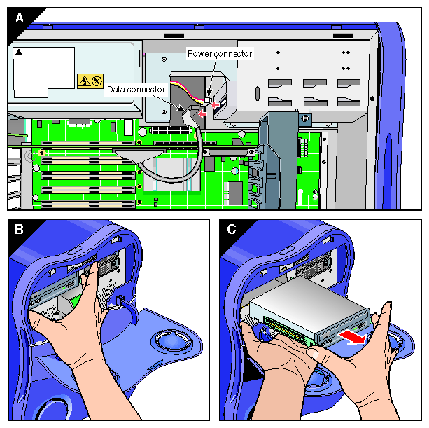
Connect the IDE cable as follows (see Figure 3-14):
Insert one end of the IDE cable into the IDE connector on the rear of the drive.
Open the latches of the IDE connector on the IO9 board. Then, insert the other end of the IDE cable into the IO9 board IDE connector.
Close the latches on the IO9 board IDE connector. Press the IO9 board into the interface board connectors to ensure that it is properly seated.
Connect the power cable to the rear of the drive (see Figure 3-14).
This completes the DVD_ROM drive installation. To return the workstation to service, see “Returning the Workstation to Service”.
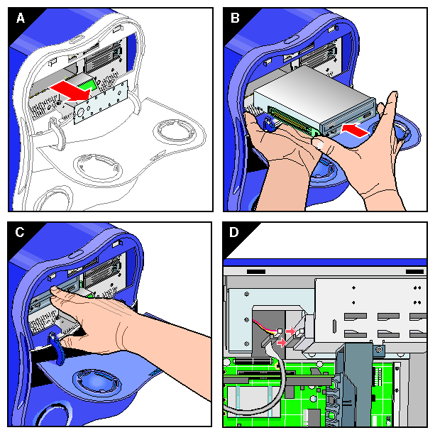
Follow these steps to remove the DVD-ROM drive:
| Note: You must remove the drive shroud before you can remove the DVD-ROM drive. |
Disconnect the IDE and power cables from the rear of the DVD-ROM drive.
Squeeze the tabs on the drive rails against the sides of the drive. Then slide the drive out of the drive cage (see Figure 3-15).
If you are replacing the drive with a new drive, refer to “Installing the DVD-ROM Drive ”. If you are not replacing the DVD-ROM drive, install a metal drive bay blanking plate in the DVD-ROM drive bay and a plastic blanking plate in the drive shroud to ensure proper airflow.
This completes the removal of the DVD-ROM drive. To return the workstation to service, refer to “Returning the Workstation to Service”.
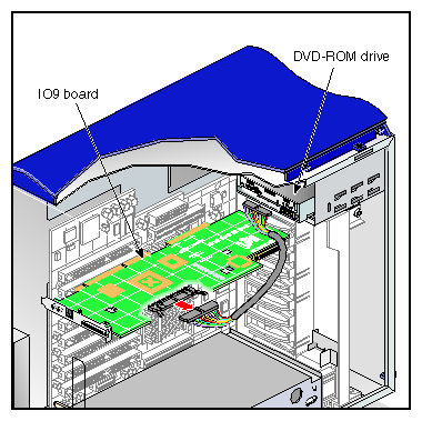
The IO9 board provides basic I/O functions for the workstation. It also provides connectivity between the hard-disk drives, DVD-ROM drive, and the interface board. The following instructions show you how to remove and install the IO9 board:
-
Note: If you remove the IO9 board, you must install a replacement IO9 board. The workstation will not function without the IO9 board installed. Note: If you have not already done so, prepare your system for service. Refer to “Preparing the Workstation for Service”. In order to replace the IO9 board, you must remove the left side panel.
Follow these steps to remove the IO9 board:
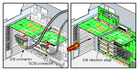
Disconnect the SCSI and IDE cables from the IO9 board. Then loosen the PCI retention strap (see Figure 3-16).
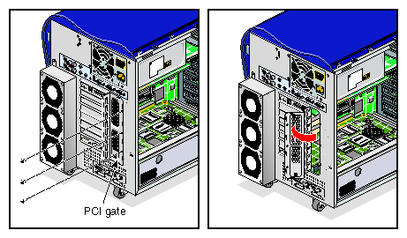
Remove the three screws that secure the PCI gate. Then open the PCI gate (see Figure 3-17).
Gently grasp both ends of the IO9 board. Then lift straight up until it clears the PCI slot. Tilt the front end of the IO9 board upward until it clears the edge of the chassis. Then remove the IO9 board from the enclosure and place it in a safe location (see Figure 3-18).

This completes the IO9 board removal. To install a new IO9 board, proceed to the next section.
Follow these steps to install a replacement IO9 board:
Align the IO9 board with PCI slot 1 on Bus 1. Then lower the IO9 board into the enclosure. Press straight down to seat the board in the PCI connector on the interface board (see Figure 3-19).
Connect the SCSI and IDE cables to the IO9 board. To connect a cable, align the cable connector with the socket on the IO9 board and press down. Then attach the retention strap to the IO9 board (see Figure 3-20).
Note: The connectors and sockets are keyed. Ensure that you have properly aligned the connect and socket before you attempt to connect them. Ensure that the IO9 board is properly aligned in the PCI gate. Then close the gate and install the three screws that secure it to the enclosure (see Figure 3-21).

This completes the installation of the IO9 board. To return the workstation to service, refer to “Returning the Workstation to Service”.
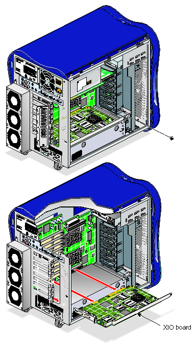
A optional XIO board can be installed in the XIO slot on the interface board. In order to install an XIO board, PCI bus 4, slot 2 must be empty. Some XIO boards require the installation of a support bracket on the fan wall. See the following sections for installation and removal instructions:
-
Note: If you have not already done so, prepare your system for service. Refer to “Preparing the Workstation for Service”. In order to install or remove an XIO board, you must remove the left side panel. Note: XIO option boards can only be installed in 2- or 4-processor workstations.
If your XIO board was shipped with a support bracket, follow these steps to install the bracket on the fan wall (see Figure 3-22):
Remove the fan wall from the enclosure. See “Replacing the Fan Wall ” for complete instructions.
Place the fan wall on a flat surface; Then align the hooks on the support bracket with the corresponding holes in the fan wall.
Insert the hooks into the holes on the fan wall; then press down until the bracket snaps into place.
Install the fan wall in the enclosure. See “Replacing the Fan Wall ” for complete instructions.
This completes the installation of the XIO board support bracket. Proceed to the next section to install an XIO board.
If your XIO board was shipped with a support bracket, install the bracket on the fan wall. See “Installing the XIO Board Support Bracket” for complete instructions.
Remove the three screws that secure the PCI gate. Then open the PCI gate (see Figure 3-26).
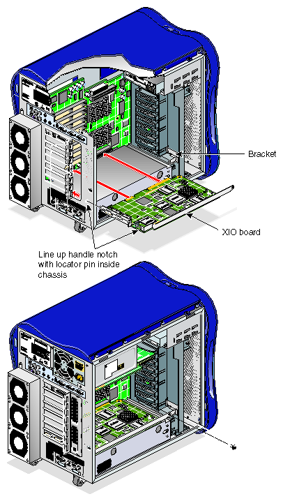
Align the board with the XIO slot. Then lower the board into the enclosure.
Press the board straight into the XIO connector on the interface board. Then install the screw that secures the XIO board to the support bracket (see Figure 3-24).
Ensure that the board is properly aligned in the PCI gate. Then close the gate and install the three screws that secure it to the enclosure (see Figure 3-25).
Note: If the XIO board you are installing is equipped with metal handle, ensure that the notch in the handle is aligned with the locator pin in the enclosure before closing the PCI gate (see Figure 3-25).
This completes the installation of the XIO board. To return the workstation to service, refer to “Returning the Workstation to Service”.
Follow these steps to remove an XIO board:
Remove the three screws that secure the PCI gate. Then open the PCI gate (see Figure 3-26).
If the XIO board you are removing is equipped with a support bracket, remove the screw that secures the board to the bracket.
Gently grasp both ends of the XIO board. Then pull straight out until it clears the XIO slot. Tilt the front end of the board upward until it clears the edge of the chassis. Then remove the board from enclosure and place it in a safe location (see Figure 3-27).
This completes the XIO board removal. To install a new board, see “Installing an XIO Board ”. To return the workstation to service, see “Returning the Workstation to Service”.
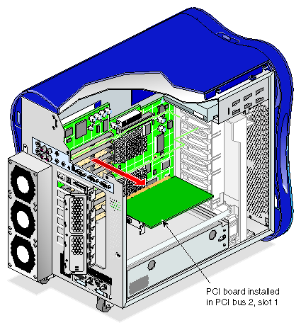
The 2- and 4-processor workstations can support as many as eight PCI/PCI-X boards. The 1-processor workstation supports as many as four PCI/PCI-X boards. The IO9 board always occupies one PCI-X slot, leaving seven available slots in 2- and 4-processor workstations and three available slots in 1-processor workstations. These instructions assume that you know the correct bus and slot you need to install the PCI board in. For more information about PCI board placement rules and configurations, refer to “PCI Buses” in Chapter 2.
| Note: If you have not already done so, prepare your system for service. Refer to “Preparing the Workstation for Service”. In order to install or remove a PCI board, you must remove the left side panel. |
This section provides instructions for the following procedures:
-
Note: All of the figures in these sections depict 2- or 4-processor workstations. PCI buses 3 and 4 are not present in 1-processor workstations.
Follow these steps to install a PCI board:
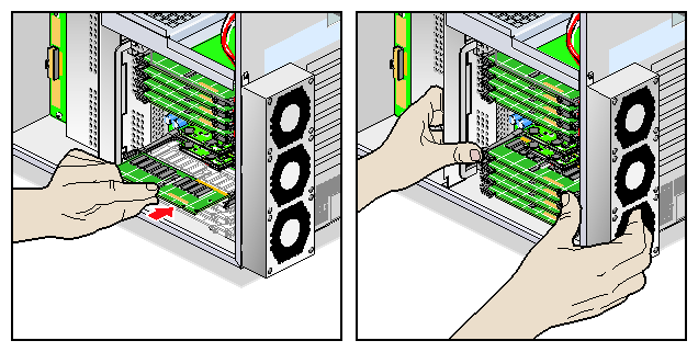
Remove the three screws that secure the PCI gate to the enclosure. Then open the PCI gate (see Figure 3-28).
If another PCI board is installed in the slot where you will install the new PCI board, you must remove it before you can install the new PCI board. See “Removing a PCI Board”.
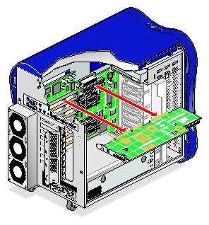
Note: If you are installing a full-length PCI board, you must also install a PCI board retention strap. Align the PCI board with the PCI slot. Then lower it into the enclosure with the connector end angled slightly downward (see Figure 3-29).
Align the connector end of the PCI board in the opening in the enclosure. Ensure that the screw hole in the PCI connector plate aligns with the tab on the PCI gate. Then press down firmly on the PCI board until it is fully seated in the PCI slot (see Figure 3-29).
Repeat steps 3 through 4 to install another PCI board.
Close the PCI gate. Then install the three screws that secure the PCI gate (see Figure 3-30).

This completes the PCI board installation. To return the workstation to service, refer to “Returning the Workstation to Service”.
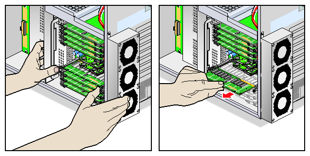
Follow these steps to remove a PCI board:
Remove the three screws that secure the PCI gate to the enclosure. Then open the PCI gate (see Figure 3-31).
If there is a retention strap installed on the PCI board, loosen it. Grasp the top edge of the PCI board firmly. Then lift the PCI board straight up until it clears the PCI slot.
Tilt the front end of the PCI board upward until it clears the edge of the chassis. Remove the PCI board from the enclosure and place it in a safe location (see Figure 3-32).
If you will be replacing the PCI board, see “Installing a PCI Board ”.
If you are finished removing PCI boards, close the PCI gate. Then install the three screw that secure the gate to the enclosure.
This completes the PCI board removal. To return the workstation to service, refer to “Returning the Workstation to Service”.
Refer to the documentation that came with the device for more information on connecting it to your workstation.
This section provides instructions for the following procedures:
“Replacing the Rear Fan Assembly ”
Caution: Never operate the unit without all of the cooling system components in place. Operating the workstation without the proper cooling equipment may damage the internal components.
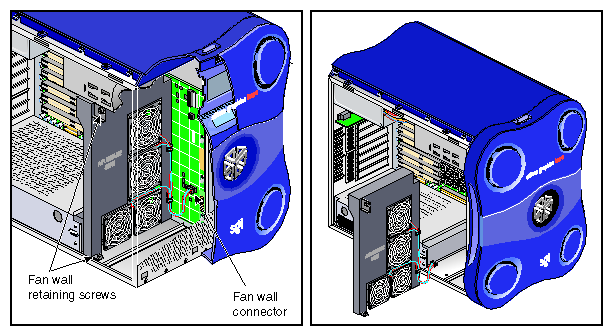
The fan wall cools the interface board, the PCI boards, and the graphics module. Follow these steps to replace the fan wall (see Figure 3-33).
| Note: If you have not already done so, prepare your system for service. Refer to “Preparing the Workstation for Service”. In order to remove the fan wall, you must remove the left side panel. |
Disconnect the fan wall power cable from the interface board. Then remove the screw that secures the fan wall to the chassis. If there is an XIO board support bracket installed on the fan wall, remove the screw that secures the XIO board to the support bracket.
Slide the fan wall straight out of the chassis. Place it in a secure location.
Slide the replacement fan wall into the enclosure. Then install the screw that secures the fan wall to the chassis.
Connect the fan wall power cable to the fan wall power connector on the interface board.
Note: If your fan wall is equipped with an XIO board support bracket, you must remove the bracket from the old fan wall and install it on the new fan wall. See “Installing the XIO Board Support Bracket”
This completes the fan wall replacement. To return the workstation to service, see to “Returning the Workstation to Service”.
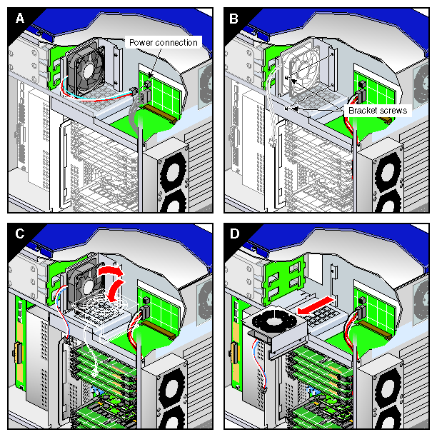
Follow these steps to replace the hard disk drive fan:
| Note: If you have not already done so, prepare your system for service. Refer to “Preparing the Workstation for Service”. In order to replace the hard disk drive fan, you must remove the right side panel. |
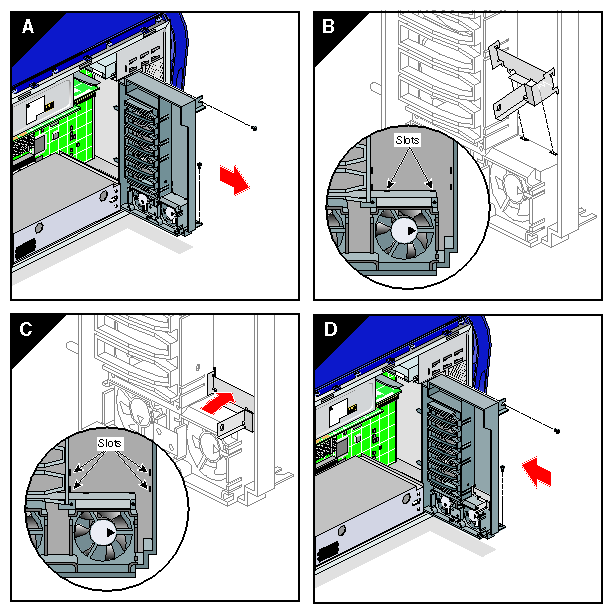
Disconnect the disk drive fan power cable from the interface board. Then remove the screws that secure the disk drive fan to the enclosure (see Figure 3-34).
Carefully remove the fan from the enclosure (see Figure 3-34).
Insert the new fan assembly into the enclosure (see Figure 3-35).
Align the screw holes in the fan bracket with the holes in the enclosure frame. Ensure that the front edge of the fan bracket has engaged with the fan bracket hook. Then install the screws that secure the fan bracket to the enclosure (see Figure 3-35).
Connect the disk drive fan power cable to the interface board (see Figure 3-35).
This completes the replacement of the hard disk drive fan. To return the workstation to service, see “Returning the Workstation to Service”.
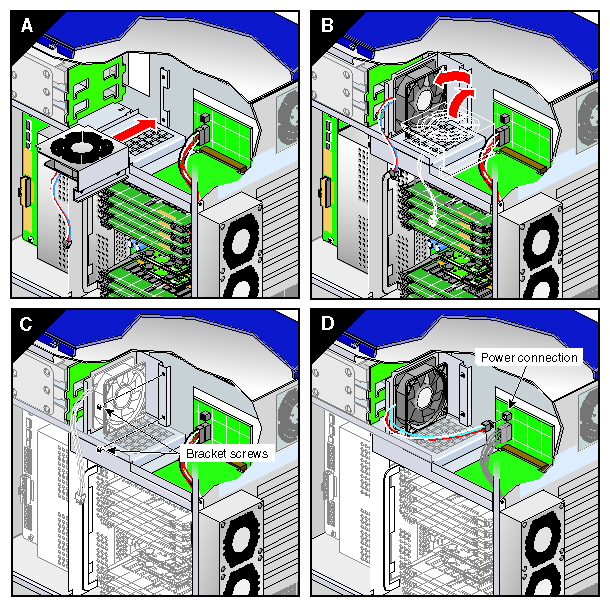
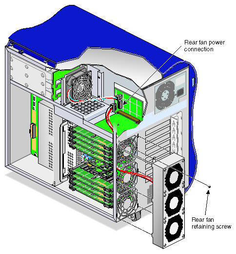
Follow these steps to replace the rear fan assembly (see Figure 3-36):
| Note: If you have not already done so, prepare your system for service. Refer to “Preparing the Workstation for Service”. In order to replace the rear fan assembly, you must remove the right side panel. |
Disconnect the rear fan assembly power cable from the interface board. Then remove the screw that secures the rear fan assembly to the enclosure.
Grasp the sides of the fan assembly and slide it upward until the hooks clear the holes in the enclosure.
Carefully pull the fan assembly power cable through the hole in the rear of the enclosure. Place the fan assembly in a secure location.
Insert the power cable of the replacement rear fan assembly into the hole in the rear of the enclosure from which you removed the old power cable.
Align the hooks and screw hole on the replacement fan assembly with the holes in the enclosure.
Insert the hooks on the fan assembly into the holes on the enclosure. Slide the fan assembly downward to firmly seat the hooks.
Install the screw that secures the rear fan assembly to the enclosure. Then connect the rear fan assembly power cable to the interface board.
This completes the replacement of the rear fan assembly. To return the workstation to service, see “Returning the Workstation to Service”.
The following sections contain instructions for replacing internal cables:
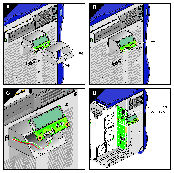
Follow the steps in this section to replace the L1 display cable.
| Note: If you have not already done so, prepare your system for service. Refer to “Preparing the Workstation for Service”. In order to replace the L1 display cable, you must remove the left side panel and the bezel. |
Remove the two screws that secure the L1 display bracket to the enclosure. Then remove the outer cover from the L1 display.
Lift the L1 display bracket upward until the hooks on the bracket clear the holes in the enclosure (see Figure 3-37).
Carefully remove the two screws that mount the L1 display board to the bracket. Then, grasping the display board by the edges, separate the display board from the bracket (see Figure 3-37).
Gently disconnect the L1 display cable from the display board. Place the L1 display board in a secure location (see Figure 3-37).
Disconnect the L1 display cable from the interface board. Then gently pry the grommet out of the hole in front of the enclosure and remove it from the cable.
Carefully push the L1 display cable into the hole in the front of the enclosure. Then remove the cable from inside the enclosure (see Figure 3-37).
If the replacement L1 display cable does not already have a grommet installed on it, install the grommet now.
Push the L1 display board connector of the replacement L1 display cable out through the hole in the front of the enclosure. Then seat the grommet in the hole (see Figure 3-38).
Connect the replacement L1 display cable to the interface board and the L1 display board (see Figure 3-38).
Install the two screws that secure the L1 display board to its bracket (see Figure 3-38).
Align the hooks on the bracket with the holes in the enclosure. Insert the hooks into the holes, and press down to seat the housing on the front of the enclosure (see Figure 3-38).
Slide the outer cover over the L1 display bracket. Then install the two screws that secure the L1 display bracket to the front of the enclosure (see Figure 3-38).
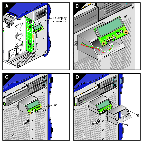
This completes the replacement of the L1 display cable. To return the workstation to service, see to “Returning the Workstation to Service”.
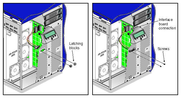
Follow these steps to replace the LED cable (see Figure 3-39).
| Note: If you have not already done so, prepare your system for service. Refer to “Preparing the Workstation for Service”. In order to replace the LED cable, you must remove the left side panel and the bezel. |
Disconnect the LED cable from the interface board.
Use a small phillips-blade screwdriver to remove the two screws and latch-blocks that secure the LED cable pass-through connector to the front of the enclosure. Place the screws and latch-blocks in a secure location. Then remove the LED cable from the enclosure.
Insert the new LED cable into the enclosure. Secure the pass-through connector to the front of the enclosure using the screws and latch-blocks you removed in step 2.
Connect the other end of the LED cable to the interface board.
This completes the replacement of the LED cable. To return the workstation to service, see “Returning the Workstation to Service”.
Follow the steps in this section to replace the DVD-ROM drive cable (see Figure 3-40).
| Note: If you have not already done so, prepare your system for service. Refer to “Preparing the Workstation for Service”. In order to replace the DVD-ROM drive cable, you must remove the left side panel. |
Open the latches on the DVD-ROM drive cable connector on the IO9 board. Then gently disconnect the DVD-ROM drive cable from the IO9 board.
Disconnect the other end of the DVD-ROM drive cable from the rear of the DVD-ROM drive and remove the cable from the enclosure.
Connect the replacement DVD-ROM drive cable to the rear of the DVD-ROM drive. Note that the cable is keyed: ensure that you are aligning the cable in the connector correctly.
Connect the replacement DVD-ROM drive cable to the IO9 board. Note that the cable is keyed: ensure that you are aligning the cable in the connector correctly.
Close the latches on the DVD-ROM drive cable connector. Then gently press the IO9 board into the interface board to ensure that it is firmly seated in its connectors.
This completes the replacement of the DVD-ROM drive cable. To return the workstation to service, see “Returning the Workstation to Service”.
This section provides instructions for the following procedures:
This section contains the following procedures:
See “Removing the Enclosure Bezel ” and “Installing the Bezel ” for instructions on replacing the bezel assembly.
See “Removing the Left or Right Side Pane l” and “Installing the Side Panels” for instructions on replacing the side panels.
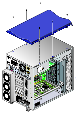
Follow these instructions to replace the top plastic of the enclosure.
| Note: If you have not already done so, prepare your system for service. Refer to “Preparing the Workstation for Service”. In order to replace the top plastic, you must remove the right and left side panels and the bezel. |
Remove the six screws that secure the top plastic to the enclosure. Then lift the top plastic off of the enclosure.
Align the holes in the replacement top plastic with the holes in the enclosure.
Install the six screws that secure the top plastic to the enclosure.
This completes the replacement of the top plastic. To return the workstation to service, see to “Returning the Workstation to Service”.
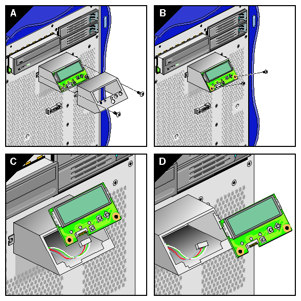
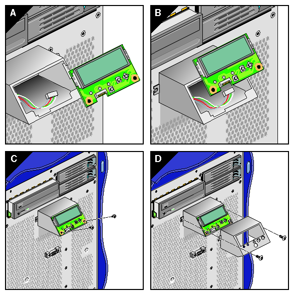
Follow the steps in this section to replace the L1 display.
| Note: If you have not already done so, prepare your system for service. Refer to “Preparing the Workstation for Service”. In order to replace the L1 display, you must remove the bezel. |
Remove the two screws that secure the L1 display bracket to the enclosure. Then slide the outside cover off of the L1 display (see Figure 3-42).
Lift the L1 display housing upward until the hooks on the housing clear the holes in the enclosure (see Figure 3-42).
Carefully remove the two screws that mount the L1 display board to its housing. Then, grasping the display board by the edges, separate the display board from the housing (see Figure 3-42).
Gently disconnect the L1 display cable from the L1 display board. Place the L1 display board in a secure location (see Figure 3-42).
Connect the L1 display cable to the replacement L1 display board (see Figure 3-43).
Install the two screws that secure the L1 display board to its bracket (see Figure 3-43).
Align the hooks on the bracket with the holes in the enclosure. Insert the hooks into the holes, and then press down to seat the bracket on the front of the enclosure (see Figure 3-43).
Slide the outside cover over the L1 display. Then install the two screws that secure the L1 display to the front of the enclosure (see Figure 3-43).
This completes the replacement of the L1 display board. To return the workstation to service, see “Returning the Workstation to Service”.