This chapter describes the function and physical components of the R-brick in the following sections:
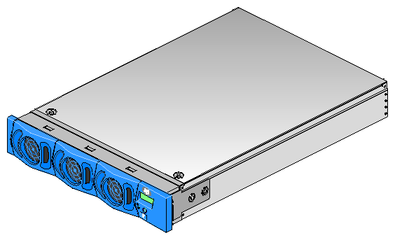
The R-brick (router brick) is an eight-port router that functions as a high-speed switch to route network packets from one C-brick to another throughout the NUMAlink interconnect fabric. Figure 8-1 shows a front view of the R-brick.
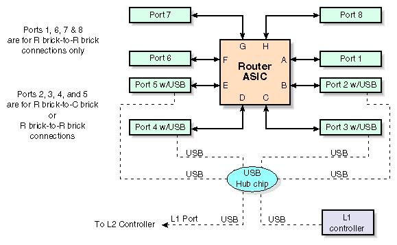
The key component within the R-brick is the router chip, an SGI custom-designed ASIC. The router chip is an eight-port crossbar that connects any input-link channel to any of the seven possible output-link channels.
The R-brick has the following features:
Eight 1.6-GB/s (each direction) NUMAlink channels
One USB port for system controller support
One L1 controller and LCD display
Two hot-pluggable cooling fans
Figure 8-2 shows a block diagram of the R-brick.
This section describes the external components that are located on the front and rear panels of the R-brick.
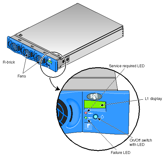
The R-brick contains the following front panel items (see Figure 8-3):
L1 display. The L1 display is a 55.7 mm X 32 mm backlit liquid crystal display (LCD) that displays system messages. It displays two lines with a maximum of 12 characters on each line.
On/Off switch with LED. Press this button to turn on the R-brick internal components. You can also turn on the R-brick internal components at a system console. If your system has a L2 controller, you can turn on the R-brick internal components at the L2 controller touch display.
Three LEDs:
On/Off switch LED. This LED illuminates green when the R-brick internal components are on and turns off when they are off.
Service required LED. This LED illuminates orange to indicate that an item is broken or not operating properly (for example, a fan is off), but the R-brick is still operating.
Failure LED. This LED illuminates red to indicate that a system failure has occurred and the R-brick is down.
Fans. Two hot-pluggable fans provide N+1 redundant cooling.
The R-brick has the following rear panel items (see Figure 5-4):
Power switch. Move the power switch to the I position to power on the L1 controller within the R-brick, and to the 0 position to power off the L1 controller. Powering on the L1 controller Illuminates the 12-VDC LED green.
PWR (power) connector. This connects the R-brick to the power bay, to provide 12-VDC and 48-VDC power to the R-brick.
48-VDC and 12-VDC LEDs. The power switch must be in the ON (I) position for these LEDs to be on. The 12-VDC LED illuminates green when the L1 controller is powered on and operating, and the 48-VDC LED illuminates green when the rest of the R-brick internal components are powered on and operating. You power on the internal components by pressing the On/Off switch on the L1 controller panel.
Links R TO R connectors (1, 6, 7, and 8, or A, F, G, and H). These link connectors connect the R-brick to other R-bricks in the network fabric.
Links R to R and C to R connectors (2, 3, 4, and 5 or B, C, D, and E). These link connectors normally connect the R-brick to C-bricks; however, in larger systems they are also used to connect R-bricks to R-bricks.
L1 port connector. This connects the internal USB hub of the R-brick to the L2 controller. The internal USB hub receives the USB signals from the L2 controller via this port and distributes these signals to the L1 controllers of the attached C-bricks and to the internal L1 controller of the R-brick.
Link connector LEDs. Each NUMAlink connector has two LEDs, as follows:
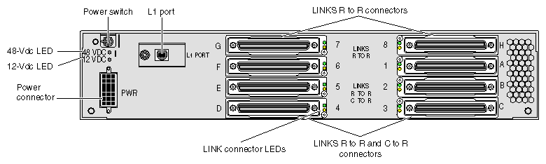
Table 8-1 lists the technical specifications of the R-brick.
Table 8-1. R-brick Technical Specifications
Characteristic | Specification |
|---|---|
Height | 3.3 in. (83.82 mm) |
Width | 17.38 in. (441.45 mm) |
Depth | 27.5 in. (698.50 mm) |
Weight | 20 lb (9.1 kg) |
Input power | 48 VDC (~ 60 W) |
Table 8-2 lists the specifications of the R-brick ports.
Table 8-2. R-brick Port Specifications
Port | Quantity | Peak Transfer Rate |
|---|---|---|
link | 8 | 1.6 GB/s each direction |
L1 | 1 | 12 Mbits/s |