This chapter describes the function and physical components of the X-brick in the following sections:
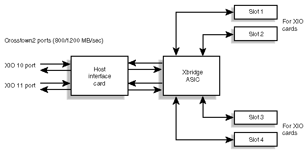
The 4U X-brick is an I/O expansion brick that provides an XIO interface for your SGI Origin 3900 server. This brick has four XIO slots (labeled 1, 2, 3, and 4) that support a variety of XIO adapter cards.
| Note: Ask your SGI sales representative for a current listing of XIO cards supported by SGI. |
Each XIO slot can support one card with maximum power levels of 50 W.
| Warning: Only qualified SGI system support engineers (SSEs) can install and replace XIO cards. |
The X-brick also contains two Crosstown2 ports and an Xbridge ASIC. Each Crosstown2 port can connect the X-brick to an IP53 node board. The Xbridge ASIC is the interface between the X-brick's two Crosstown2 ports and the slots for the XIO cards, as shown in Figure 6-1.
This section describes the external components located on the front and rear panels of the X-brick.
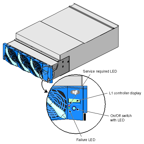
The X-brick has the following front-panel components (see Figure 6-2):
L1 controller display. This liquid crystal display (LCD) displays status and error messages that the L1 controller generates.
On/Off switch with LED. Press this button to turn on the X–brick internal components. Alternatively, you can turn on the X–brick internal components at a system console.
L1 controller switches and LEDs:
On/Off switch LED. Illuminates green when the internal components are on.
Service required LED. Illuminates orange to indicate that an item is broken or not operating properly, but the X-brick is still operating.
Failure LED. Illuminates red to indicate that a system failure has occurred and the X-brick is not operating.
Fans. Three hot-swappable fans provide the required cooling for the X-brick.

Warning: To prevent personal injury, or damage to the X-brick, the fans can be installed only by a trained SGI system support engineer (SSE).
The X-brick has the following rear-panel components (see Figure 6-3).
Power switch. Moving the power switch to the 1 position powers on the L1 controller of the X-brick, and moving it to the 0 position powers off the L1 controller.
12-VDC LED. The 12-VDC LED illuminates green when the L1 controller is powered on.
48-VDC LED. The power switch must be in the ON (1) position for this LED to illuminate. The 48-VDC LED illuminates green when the rest of the X-brick internal components are powered on.
PWR (power) connector. This connector connects to a power bay, which provides power to the X-brick.
XIO card slots. These slots seat the XIO cards. The slots are numbered 1 through 4 as shown in Figure 6-3. Each slot can seat one XIO card with power levels up to 50 W.
Warning: To avoid personal injury or damage to your system, only qualified SGI system support engineers (SSEs) can install and replace XIO cards. XIO 10 and XIO 11 connectors. Each connector can connect the X-brick to one IP53 node board. As an option, the second connector can connect to another IP53 node board to create a dual-ported X-brick, which provides greater bandwidth.
XIO 10 and XIO 11 connector LEDs. Each connector has two LEDs, as follows:
The yellow LED illuminates to indicate that both the X-brick and the IP53 node board to which it is connected are powered on.
The green LED illuminates when a link has been established between the X-brick and the IP53 node board to which it connects.
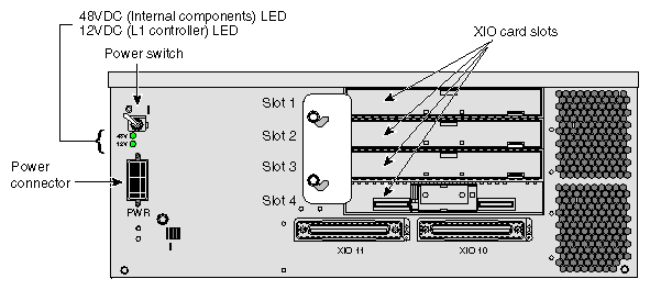
Table 6-1 lists the technical specifications of the X-brick.
Table 6-1. X-brick Technical Specifications
Characteristic | Specification |
|---|---|
Height | 6.64 in. (168.65 mm) |
Width | 17.5 in. (444.5 mm) |
Depth | 27.74 in. (698.50 mm) |
Weight | 69 lb (31.29 kg) |
Input power | 48 VDC (~225 W) |