This chapter tells you how to install and remove single inline memory modules (SIMMs). You may need to remove and replace SIMMs if you are upgrading the memory in your system. Also, if diagnostic tests report failures, or if you get memory parity errors (see Chapter 7, “Installing and Removing Software”), you may need to remove and replace SIMMs.
Many customers order additional memory for their systems. You may have received extra SIMMs with your Indigo2 IMPACT shipment or later in a separate package.
Carefully follow all steps in the following sections to shut down your system, remove the cover, install the SIMMs, replace the cover, and test to make sure the SIMMs are installed and working properly.
Refer to Chapter 5, “Identifying, Installing, and Removing Graphics Boards and Attached Option Boards,” for instructions on removing and replacing the texture memory option board.
To shut down and power off the system, follow these steps:
Open the front cover.
Press and release the power switch on the front of the system to shut down the software and power off the system.
The system powers off automatically.
Press the monitor power switch to turn off your monitor.
Disconnect the power cable from the back of the Indigo2 IMPACT workstation.

Once the system is shut down and the power cable is disconnected, follow these steps:
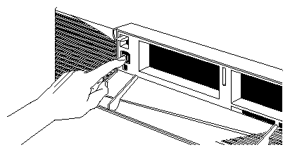
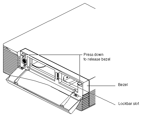
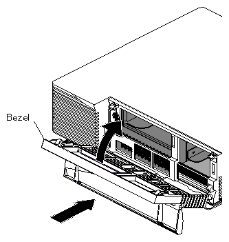
Remove the bezel.
Press down on the tabs on each side of the bezel, as shown in Figure 3-3.
Remove the lockbar if you have one installed.
Remove the lock from the exterior rear of the workstation.
Slide the lockbar out of the bezel.
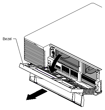
Pull the bezel down and away from the chassis.
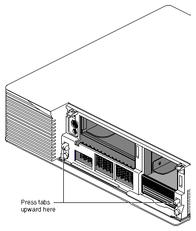
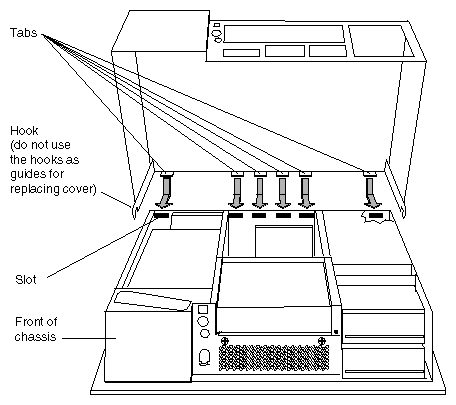
Press up on the tabs on each side of the drive openings, as shown in Figure 3-5.
Pull up on the cover and lift it back and away from the chassis, as shown in Figure 3-6.
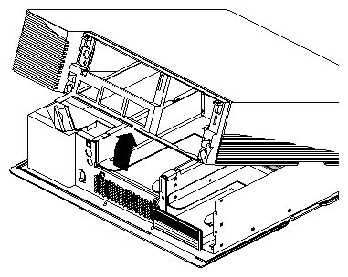
 | Tip: If the cover is difficult to raise, check the locking levers of your drives to be sure they are fully locked. The levers should be pushed all the way to the right. |
To install SIMMs, follow these steps:
Attach the wrist strap.
Unwrap the first two folds of the band and wrap the exposed adhesive side firmly around your wrist.
Unroll the rest of the band and peel the liner from the copper foil at the opposite end.
Attach the copper foil to a convenient and exposed electrical ground, such as a metal part of the Indigo2 IMPACT workstation.

Caution: The workstation's internal components are sensitive to static electricity. Handle the parts carefully, and wear the wrist strap to avoid the flow of static electricity. Turn the workstation so that you face the rear of the chassis. The SIMM sockets are in the center of the workstation, toward the back of the chassis, as shown in Figure 3-7.
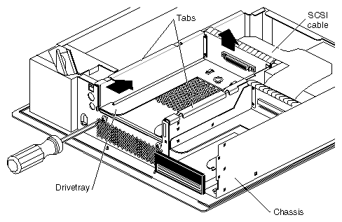
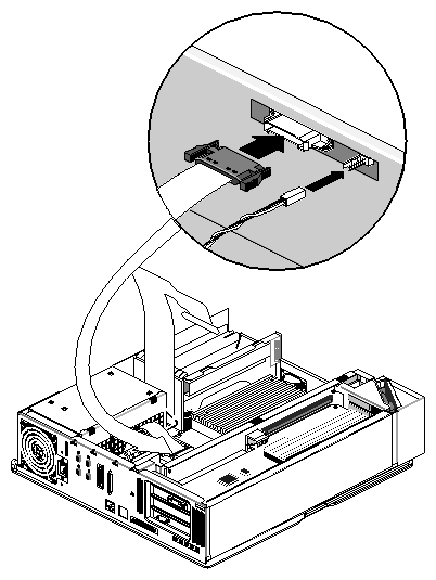
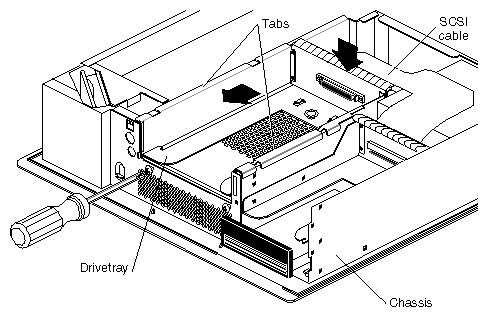
Disconnect the SCSI cable, power cable, and twisted-pair cable to allow yourself better access to the SIMM slots. See Figure 3-8.
Disconnect the SCSI cable from the back of the 5-1/4" drive tray. The drive tray is located above and to the rear of the SIMM sockets.
Unclip the wire clips on the SCSI cable from the edges of the connector and disconnect the SCSI cable from the connector on the back of the drive tray.
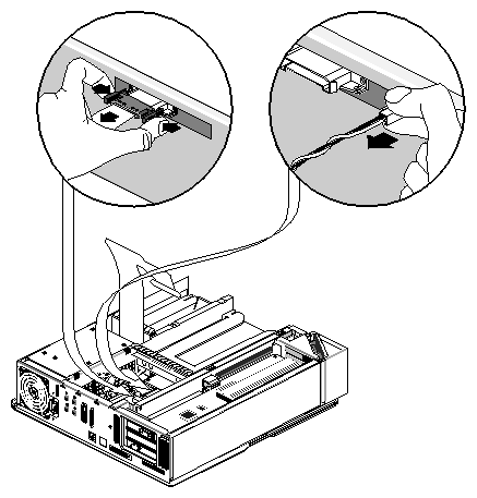
Disconnect the midplane power cables (ribbon and twisted pair) from the gold-colored midplane. These cables cross the SIMM sockets and connect the power supply to the midplane.

Note: If you have an IMPACT Ready Indigo2 workstation, you will not disconnect and connect these cables, because they terminate to the power supply. Pinch together the corrugated edges on the ribbon cable connector, and pull gently to disconnect it from the midplane. See Figure 3-9.
Pull gently on the twisted-pair connector to disconnect it from the midplane. See Figure 3-9.
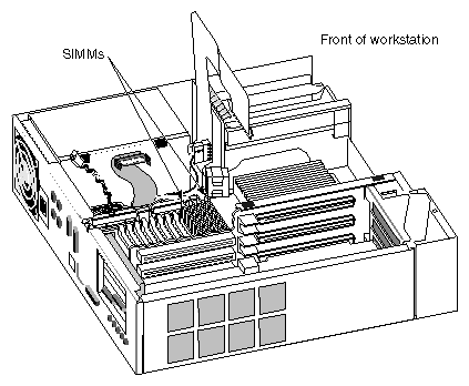
Twelve sockets are split into three banks—A, B, and C. The four sockets closest to the center of the workstation make up Bank C. The next four sockets make up Bank B. The four sockets closest to the rear of the chassis make up Bank A. The banks are labeled on the baseboard. See Figure 3-10.
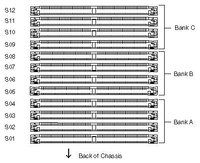
The SIMM sockets are labeled from 1 through 12, beginning with the first slot in Bank A. The sockets are labeled on the baseboard.
| Note: If you are installing SIMMs in bank C, you must remove the 5-1/4" drive tray first, before installing the SIMMs. Turn to “Removing the 5-1/4" Drive Tray” for instructions. |
Install the first SIMM.
Install SIMMs consecutively, in groups of four, beginning with the open slot farthest away from you (from Bank C to Bank A). For example, if Bank C is full, beginning installing SIMMs in S08, the slot in Bank B that is closest to Bank C. (See Figure 3-10.)
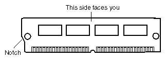
Note: All the SIMMs in a bank must be the same size. Facing the rear of the workstation and using both hands, grasp the top of the SIMM so the notch in the bottom corner of the SIMM is on your left, as shown in Figure 3-11.
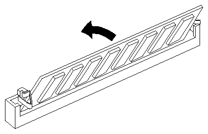
Tip the top of the SIMM toward you, as shown in Figure 3-12, and press the SIMM securely into the socket at a 45-degree angle to the board.
Tilt the SIMM up into a vertical position.
The SIMM is positioned correctly when the latches on both sides of the SIMM socket are hugging the edges of the SIMM.
Install the other SIMMs.
Visually check the tops of the SIMMs to make sure they are installed correctly.
If a SIMM is not sitting vertically, push it upward until it is completely vertical.
Reconnect the power cable and twisted pair cable to the gold-colored midplane. See Figure 3-13.
Note: If you have an IMPACT Ready Indigo2 workstation, you will not disconnect and reconnect these cables, because they terminate to the power supply. If you removed the drive tray, turn the workstation so you are facing the front and replace the drive tray. See “Replacing the 5-1/4" Drive Tray”.
Reconnect the SCSI cable on the back of the 5-1/4" drive tray.
Push the SCSI cable into the connector on the back of the drive tray.
Slip the wire clips on the SCSI cable over the edges of the connector to hold the SCSI cable securely in place.
You are ready to replace the cover.
It is important to replace the cover before testing the SIMMs. This ensures proper airflow through the workstation while the system is running the test.
To replace the cover, follow these steps:
Locate the tabs on the inside and back of the top cover, and the holes on the back of the workstation. Figure 3-14.
Replace the bezel.
Place the tabs on the bottom of the bezel in the grooves in the front of the chassis. See Figure 3-15.
Tilt the bezel up until it snaps into place.
Replace the lockbar if you removed it.
Close the front cover of the bezel.
Reconnect the power cable to the connector on the back of the workstation.
You are ready to power on the system and check the new memory.
Make sure the system recognizes the new memory. To check the amount of memory on your system, follow these steps:
If your Indigo2 IMPACT workstation is new, make sure you've already installed the system disk before turning on the system.
Press the power switch to turn on the power.
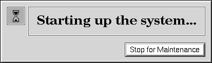
After the power-on diagnostics run, you'll see a notifier, as shown in Figure 3-16.
After a few seconds, you see the notifier shown in Figure 3-17.
The system boots and brings up the login screen.
If no picture appears on your screen and the yellow fault light blinks, one or more SIMMs are not installed correctly. Turn off the system, remove the cover, and check that the SIMMs are installed correctly. Then try this procedure again. If it still fails, see Chapter 7, “Installing and Removing Software.”
Log in to your account. For more information on logging in, refer to “Logging In to the Workstation”.
When you log in, the default desk appears. In the upper left-hand corner of the screen are the toolchests.
Choose “System Manager” from the System toolchest.
You see a window showing Hardware and Shared Resources.
Look under the Hardware listing for the line showing memory. The amount of memory shown in megabytes should equal the amount of memory that came with the workstation plus the amount of memory you installed.
For example, if you had 32 MB of memory on the workstation when you started and you installed another 32 MB, you should have a total of 64 MB.

| Note: If the amount of memory you just installed is not added to the original amount, the SIMMs are not installed correctly. Make sure that all of the SIMMs are all the way in. Return to “Installing Memory” to check the SIMMs. Then try this procedure again. |
Now you are ready to use the Indigo2 IMPACT workstation.
You may need to remove SIMMs if one fails or if you want to upgrade the memory in your system.
| Caution: SIMMs and the system's internal components are sensitive to static electricity. Handle the SIMMs carefully, and wear the wrist strap to avoid the flow of static electricity. |
To remove memory SIMMs, you must shut down the system, remove the cover, remove the 5-1/4" drive tray (if necessary), disconnect three cables, and remove the SIMMs. Then, reconnect the three cables, replace the 5-1/4" drive tray (if you removed it) and the cover. You need a Phillips screwdriver to remove the 5-1/4" drive tray.
To shut down the system, follow these steps:
Open the front cover.
Press and release the power switch on the front of the workstation to shut down the software and power off the system.
The system powers off automatically.
Disconnect the power cable from the back of the workstation.
Once the system is shut down and the power cable is disconnected, follow these steps:
Remove the bezel.
Press down on the tabs on each side of the bezel, as shown in Figure 3-18.
Pull the bezel down and away from the chassis.
Remove the top cover.
Press up on the tabs on each side of the drive openings as shown in Figure 3-20.
Pull up on the cover and lift it back and away from the chassis, as shown in Figure 3-21.
| Tip: If the cover is difficult to raise, check the locking levers of your drives to be sure they are fully locked. The levers should be pushed all the way to the right. |
The SIMMs are located in the center of the workstation, toward the back, as shown in Figure 3-22.
The first few SIMMS in Bank C are located beneath the 5-1/4" drive tray. If you need to remove these SIMMs, you must first remove the drive tray. You will need a Phillips screwdriver to remove the drive tray.
If the SIMMs you are removing are not covered by the 5-1/4" drive tray, you do not need to remove the tray. Turn to “Removing the SIMMs” for instructions on how to remove the SIMMs.
To remove the 5-1/4" drive tray, follow these steps:
Ground yourself to the chassis.
Unwrap the first two folds of the band and wrap the exposed adhesive side firmly around your wrist.
Unroll the rest of the band and peel the liner from the copper foil at the opposite end.
Attach the copper foil to a convenient and exposed electrical ground, such as a metal part of the Indigo2 IMPACT workstation.
Caution: The workstation's internal components are sensitive to static electricity. Handle the parts carefully, and wear the wrist strap to avoid the flow of static electricity. Disconnect the SCSI cable from the connector on the back of the 5-1/4" drive tray.
Unclip the wire clips on the SCSI cable from the sides of the connector and disconnect the SCSI cable from the connector on the back of the drive tray.
Use a Phillips screwdriver to loosen the two captive screws holding the 5-1/4" drive tray to the chassis.
Note: If a drive is installed, you do not need to remove it. Push the drive tray assembly backward, and pull up to remove it, as shown in Figure 3-23.
To remove the SIMMs, follow these steps:
Make sure your wrist strap is attached to a metal part of the chassis and the elastic is secure around your arm.
Note: If you have an IMPACT Ready Indigo2 workstation, you will not disconnect and connect these cables. Disconnect the ribbon cable and twisted pair cable from the gold-colored midplane.
Pinch together the corrugated edges on the ribbon cable connector, and pull it free from the midplane. See Figure 3-24.
Pull the white lever on the midplane away from the twisted-pair connector. Pull gently on the twisted-pair connector to disconnect it from the midplane.
Remove the SIMMs.
Face the back of the workstation.
Locate the memory SIMMs you want to remove.
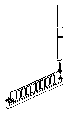
Note: In order to replace a faulty SIMM, you need to first remove the SIMM closest to the rear of the chassis, then remove the following SIMMs until you reach the SIMM you want to replace. Use the SIMM removal tool that came with your SIMMs. Place the flat side of the tool against the side of the SIMM (as shown in Figure 3-25) and press down on the latches on each side of the SIMM.
The SIMM releases and tips toward you about 45 degrees.
Pull the SIMM out of the socket.
Remove the other SIMMs.
To replace the SIMMs, turn to “Installing the SIMMs”.
If you are not replacing SIMMs, go to the next step.
If you are not replacing SIMMs, reconnect the ribbon cable and twisted pair cable to the gold-colored midplane.
Pinch together the corrugated edges on the ribbon cable connector, and connect it to the midplane. See Figure 3-26.
Push the twisted-pair connector gently into its connector on the midplane.
If you removed the drive tray, follow these steps to replace it:
Make sure your wrist strap is attached to a metal part of the chassis and the elastic is secure around your arm.
Replace the 5-1/4" drive tray assembly.
Position the drive and tray so the tabs on the sides of the tray fit inside the slot openings in the chassis, and the open side of the tray faces the front of the workstation. See Figure 3-27.
Push the tray forward about 1/2" to lock it in place.
Tighten the two captive screws.
Reattach the SCSI cable to the connector on the back of the drive tray.
To replace the top cover, follow these steps:
Locate the tabs on the inside and back of the top cover and the slots on the back of the workstation. See Figure 3-28.
Face the front of the workstation.
Replace the bezel.
Place the tabs on the bottom of the bezel in the grooves in the front of the chassis, as shown in Figure 3-29.
Tilt the bezel up until it snaps into place.
Reinstall the lockbar.
Slide it through the bezel and out the back of the workstation.
Reattach the lock.
Close the front cover.
Reconnect the power cable to the connector on the back of the Indigo2 IMPACT workstation.
You are finished removing the SIMMs and are ready to power on the system.