This Appendix describes the steps to be taken to locate problems with an SGI Onyx4 system, and provides the procedures for the removal and replacement of user-replaceable parts.
If you are experiencing problems with your SGI Onyx4 system, you can follow the steps detailed in this section to help isolate and correct the problem.
If you are having problems with your host system you should refer to the user's manual for that host system.
For problems not addressed in this section, please contact your SGI authorized support representative.
Before proceeding to the sections addressing specific issues, follow the steps in this section.
Ensure that each graphics brick in your system is connected to AC power.
See “Providing Power to G2-bricks and G2N-bricks” in Chapter 2.
Ensure that each graphics brick in your system is powered on.
Ensure that the host system can “see” each graphics brick in your system.
Table A-1 lists recommended actions for problems that can occur on your system. For problems that are not listed in this table, use the SGI Electronic Support system to help solve your problem or contact your SGI system support engineer (SSE). More information about the SGI Electronic Support system is provided in this appendix.
Table A-1. Troubleshooting Chart
Recommended Action | |
|---|---|
The system will not power on. | Ensure that the power cord of the PDU is seated properly in the power receptacle. Ensure that the PDU circuit breaker is on. If the power cord is plugged in and the circuit breaker is on, contact your SSE. |
An individual brick will not power on. | Ensure that the power cord between the PDU and the brick is securely plugged in at both ends. View the L1 display, refer to Table A-2 if an error message is present. If the L1 controller is not running, contact your SSE. |
The system will not boot the operating system. | Contact your SSE. |
The Service Required LED illuminates on a brick. | View the L1 display of the failing brick; refer to Table A-2 for a description of the error message. |
The Failure LED illuminates on a brick. | View the L1 display of the failing brick; refer to Table A-2 for a description of the error message. |
The green or yellow LED of a NUMAlink port (rear of NUMAlink brick) is not illuminated. | Ensure that each end of the NUMAlink cable is seated properly. |
Table A-2 lists error messages that the L1 controller generates and displays on the L1 display. This display is located on the front of the brick.
| Note: In Table A-2, a voltage warning occurs when a supplied level of voltage is below or above the nominal (normal) voltage by 10 percent. A voltage fault occurs when a supplied level is below or above the nominal voltage by 20 percent. |
| Note: For more details about these environmental limits, use the L1 env command. |
Table A-2. L1 Controller Messages
L1 System Controller Message | Message Meaning and Action Needed |
|---|---|
Internal voltage messages: |
|
ATTN: x.xV high fault limit reached @ x.xxV | 30-second power-off sequence for the brick. |
ATTN: x.xV low fault limit reached @ x.xxV | 30-second power-off sequence for the brick. |
ATTN: x.xV high warning limit reached @ x.xxV | A higher than nominal voltage condition is detected. |
ATTN: x.xV low warning limit reached @ x.xxV | A lower than nominal voltage condition is detected. |
ATTN: x.xV level stabilized @ x.xV | A monitored voltage level has returned to within acceptable limits. |
Fan messages: |
|
ATTN: FAN # x fault limit reached @ xx RPM | A fan has reached its maximum RPM level. The ambient temperature may be too high. Check to see if a fan has failed. |
ATTN: FAN # x warning limit reached @ xx RPM | A fan has increased its RPM level. Check the ambient temperature. Check to see if the fan stabilizes. |
ATTN: FAN # x stabilized @ xx RPM | An increased fan RPM level has returned to normal. |
ATTN: TEMP # advisory temperature reached | The ambient temperature at the brick's air inlet has exceeded the advisory limit. |
ATTN: TEMP # critical temperature reached | The ambient temperature at the brick's air inlet has exceeded the advisory limit. |
ATTN: TEMP # fault temperature reached | The ambient temperature at the brick's air inlet has exceeded the advisory limit. |
Temperature stable message: |
|
ATTN: TEMP # stabilized @ xxC/xxF | The ambient temperature at the brick's air inlet has returned to an acceptable level. |
Power off messages: |
|
Auto power down in xx seconds | The L1 controller has registered a fault and is shutting down. The message displays every 5 seconds until shutdown. |
Base module appears to have been powered down | The L1 controller has registered a fault and has shut down. |
SGI Electronic Support provides system support and problem-solving services that function automatically, which helps resolve problems before they can affect system availability or develop into actual failures. SGI Electronic Support integrates several services so they work together to monitor your system, notify you if a problem exists, and search for solutions to the problem.
Figure A-1 shows the sequence of events that occurs if you use all of the SGI Electronic Support capabilities.
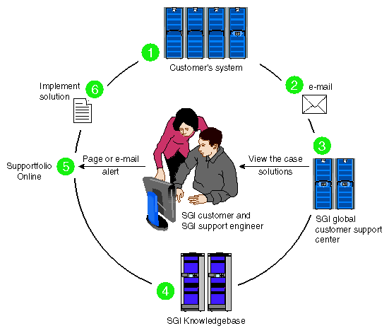
The sequence of events can be described as follows:
Embedded Support Partner (ESP) monitors your system 24 hours a day.
When a specified system event is detected, ESP notifies SGI via e-mail (plain text or encrypted).
Applications that are running at SGI analyze the information, determine whether a support case should be opened, and open a case if necessary. You and SGI support engineers are contacted (via pager or e-mail) with the case ID and problem description.
SGI Knowledgebase searches thousands of tested solutions for possible fixes to the problem. Solutions that are located in SGI Knowledgebase are attached to the service case.
You and the SGI support engineers can view and manage the case by using Supportfolio Online as well as search for additional solutions or schedule maintenance.
Implement the solution.
Most of these actions occur automatically, and you may receive solutions to problems before they affect system availability. You also may be able to return your system to service sooner if it is out of service.
In addition to the event monitoring and problem reporting, SGI Electronic Support monitors both system configuration (to help with asset management) and system availability and performance (to help with capacity planning).
The following three components compose the integrated SGI Electronic Support system:
SGI Embedded Support Partner (ESP) is a set of tools and utilities that are embedded in the IRIX operating system. ESP can monitor a single system or group of systems for system events, software and hardware failures, availability, performance, and configuration changes, and then perform actions based on those events. ESP can detect system conditions that indicate potential problems, and then alert appropriate personnel by pager, console messages, or e-mail (plain text or encrypted). You also can configure ESP to notify an SGI call center about problems; ESP then sends e-mail to SGI with information about the event.
SGI Knowledgebase is a database of solutions to problems and answers to questions that can be searched by sophisticated knowledge management tools. You can log on to SGI Knowledgebase at any time to describe a problem or ask a question. Knowledgebase searches thousands of possible causes, problem descriptions, fixes, and how-to instructions for the solutions that best match your description or question.
Supportfolio Online is a customer support resource that includes the latest information about patch sets, bug reports, and software releases.
The complete SGI Electronic Support services are available to customers who have a valid SGI Warranty, FullCare, FullExpress, or Mission-Critical support contract. To purchase a support contract that allows you to use the complete SGI Electronic Support services, contact your SGI sales representative. For more information about the various support contracts, refer to the following Web page:
http://www.sgi.com/support/customerservice.html
For more information about SGI Electronic Support, refer to the following Web page:
This section describes the parts in an SGI Onyx4 system that may be replaced by a user.
For information about parts in your host system you should refer to the user's manual for that host system.
For parts not addressed in this Appendix, please contact your SGI authorized support representative.
Before you perform any type of maintenance to your system, read the following safety instructions:
Follow all warnings and instructions marked on the product and noted in this and other documentation included with the product.
Unplug this product from the wall outlet before you clean it. Do not use liquid cleaners or aerosol cleaners. Use a damp cloth for cleaning.
Do not use this product near water.
Do not place this product or components of this product on an unstable cart, stand, or table. The product may fall, causing serious damage to the product.
Slots and openings on the cabinet and components are provided for ventilation, reliable operation, and protection from overheating of the product. These slots and openings must not be blocked or covered. This product should never be placed near or over a radiator or heat register, or in a built-in installation unless proper ventilation is provided.
This product should be operated with the type of power indicated on the marking label. If you are not sure of the type of power available, consult your dealer or local power company.
Do not allow anything to rest on the power cord. Do not locate this product where people will walk on the cord.
Do not use extension cords with your SGI system.
Never push objects of any kind into this product through cabinet slots because they may touch dangerous voltage points or short out parts that could result in a fire or electric shock.
Never spill liquid of any kind on the product.
Do not attempt to service this product yourself except as noted in this guide. Opening or removing covers of internal components may expose you to dangerous voltage points or other risks. Refer all servicing to qualified service personnel.
Unplug this product from the wall outlet and refer servicing to qualified service personnel under the following conditions:
If the power cord or plug is damaged or frayed.
If the product has been exposed to rain, water, or other type of liquid.
If the product does not operate normally when the operating instructions are followed.

Note: Adjust only those controls that are covered by the operating instructions, because improper adjustment of other controls may result in damage and will often require extensive work by a qualified technician to restore the product to normal condition. If the product has been dropped or if the cabinet has been damaged.
If the product exhibits a distinct change in performance, which indicates a need for service.
Only qualified service personnel should replace the soldered lithium battery (or batteries) in the system. Please see the “Lithium Battery Statement” in Appendix D for more information.
Use only the proper type of power supply cord set (provided with the system) for this unit.
Each G2-brick or G2N-brick contains a sled-mounted power supply (refer to Figure A-2).
This section provides the following information:
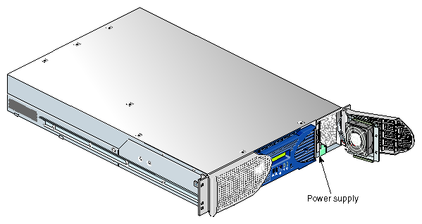
Use the LED located on the front (towards the top) of the power supply to read the condition of the power supply. Table A-3 shows the LED status and the power supply condition the LED status indicates.
Table A-3. LED Status and Power Supply Condition
LED Status | Power Supply Condition Indicated |
|---|---|
Off | Indicates that the power supply is not receiving AC power. Power supplies will not be receiving AC power because either the brick is not plugged into power, or an electrical fuse has blown. |
Amber | Indicates a fault condition for one of the following reasons: - The temperature limit has been exceeded. - The current limit has been exceeded. |
Blinking Green | The power supply is receiving AC power, but the main primary DC power has not yet activated. |
Green | The power supply is operating properly. |
To replace the power supply, follow these steps:
Power off the host system as described in the user's guide that came with your host system.

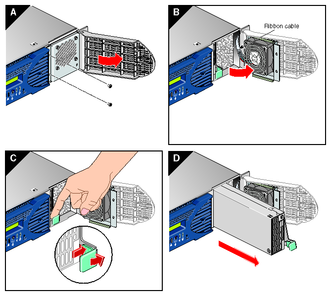
Warning: Components may be hot. To avoid injury, allow the components to cool for approximately five minutes before you proceed with these instructions. Remove the power supply, as follows:
Swing open the bezel door located on the right side of the brick front panel. With a Phillips screw driver, unscrew the two screws on the screen cover as shown in Figure A-3A.
Swing open the screen cover as shown in Figure A-3B.
Disengage the power supply from the power supply bay by pushing the interior release button to the right and pulling up and out on the green handle lock as shown in Figure A-3C.
Gently pull out the power supply from the chassis until it clears the power supply bay as shown in Figure A-3D. Place the power supply on an ESD-safe surface.

Caution: When pulling the power supply out from the chassis, make sure not to disturb the power supply fan's ribbon cable.
Install the replacement power supply, as follows:
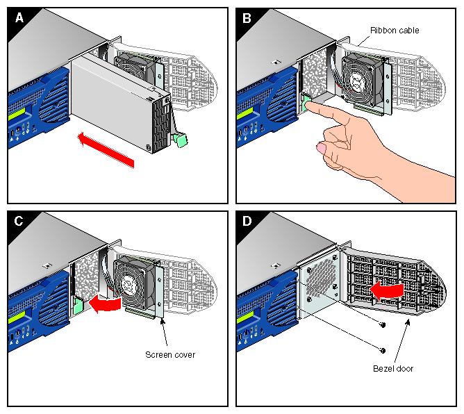
Position the power supply in the slot and with the power supply handle pulled up (fully opened), gently push the power supply into the bay as shown in Figure A-4A.
Caution: When installing the power supply, make sure that the power supply does not clip or pinch the power supply fan's ribbon cable. Push in and down on the green handle and snap the power supply into place as shown in Figure A-4B.
After you have installed the power supply, swing the screen cover until it closes as shown in Figure A-4C.
Caution: When closing the screen cover, make sure that the cover does not clip or pinch the power supply fan's ribbon cable. Screw in the two Phillips screws that you had removed as shown in Figure A-4D, and close the bezel door.
Power on the host system as described in the user's guide that came with your host system.
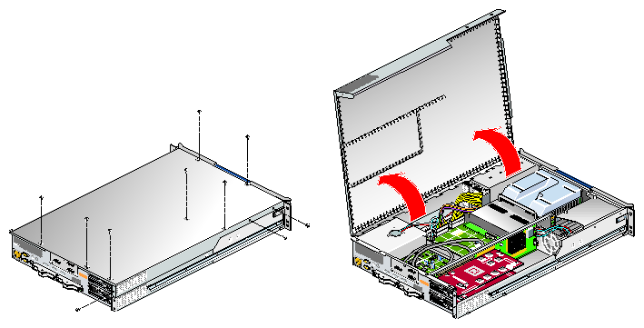
To open the chassis, follow the steps in this section.
Remove the ten Phillips screws shown in Figure A-5
Lift and open the hinged cover.
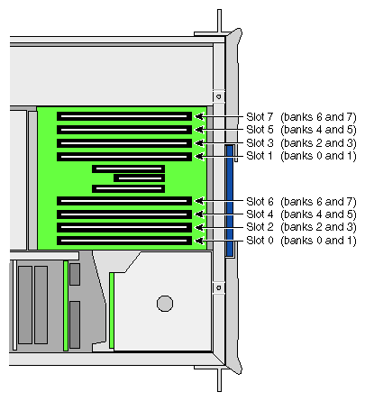
Memory is contained on cards that are referred to as DIMMs (dual inline memory modules). Each G2N-brick can contain two, four, six, or eight DIMMs installed in eight DIMM slots located in the brick.
| Note: G2N-bricks contain memory. G2-bricks, however, do not have DIMM slots, and therefore can not contain memory. |
These eight DIMM slots are physically grouped into even–numbered slots (0, 2, 4, and 6) and odd-numbered slots (1, 3, 5, and 7) as shown in Figure A-6.
DIMMs must be installed in pairs, one per DIMM slot, so that the two DIMMs installed provide local memory for the same pair of banks. For example, if you install a DIMM in slot 0, you must also install a DIMM in slot 1. (This adds memory to bank pairs 0 and 1). Table A-4 lists the DIMM slots and the corresponding bank pairs to which local memory is provided when DIMMs are installed.
Table A-4. DIMMs and Bank Pairs
DIMM in Slot Number | Provides Local Memory for Bank Pair Numbers |
|---|---|
0[a] | 0 and 1 |
1 | 0 and 1 |
2 | 2 and 3 |
3 | 2 and 3 |
4 | 4 and 5 |
5 | 4 and 5 |
6 | 6 and 7 |
7 | 6 and 7 |
[a] The first two DIMMs must be installed in DIMM slot 0 and DIMM slot 1. | |
You must note these guidelines when installing DIMMs:
Memory is increased or decreased in two-DIMM increments only.
The two DIMMs that make up a bank pair must be the same memory size; however, each pair of DIMMs can differ in memory size.
The first two DIMMs must be installed in DIMM slot 0 and DIMM slot 1. Subsequent DIMMs can be installed into any bank pairs as long as the two DIMMs are installed so that they provide local memory for the same bank pair. For example, you can install DIMMs in slots 2 and 3 to provide local memory for banks 2 and 3. Or you can install DIMMs in slots 4 and 5 to provide memory to banks 4 and 5, or you can install DIMMs in slots 6 and 7 to provide memory for banks 6 and 7.
The DIMMs used in the G2N-brick are compatible with the DIMMs used in Origin 300 and Origin 350 server system base compute modules, the system expansion compute module, and the MPX module. They are not compatible with the DIMMs used in the Origin 200, SGI 2000 series, Onyx2, or Octane systems.
The G2N-brick supports the following memory kits:
1-GB kit with integrated directory memory.
2-GB kit with integrated directory memory.
Caution: Electronic equipment can be irreparably damaged by electrostatic discharge (ESD). Always follow these preventive measures when you handle a system component:
- Remove a component from its antistatic bag only when you are ready to install it.
- If you handle a component before installation, do not place it on surfaces that produce ESD (carpeting, for example) or near devices that create static electricity.
- Attach a static wrist strap to a grounded connection on your system when you install or remove a component.
To install a DIMM, follow these steps:
Power off the host system as described in the user's guide that came with your host system.
Disconnect all of the cables at the rear of the brick.
Open the chassis as described in “Opening the Chassis”.
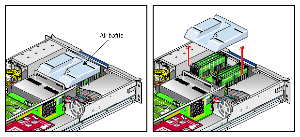
Warning: Components may be hot. To avoid injury, allow the components to cool for approximately five minutes before you proceed with these instructions. Remove the plastic air baffle covering the DIMMs, as shown in Figure A-7.
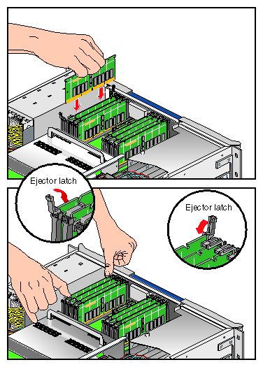
Install the DIMM, as follows (see Figure A-8):
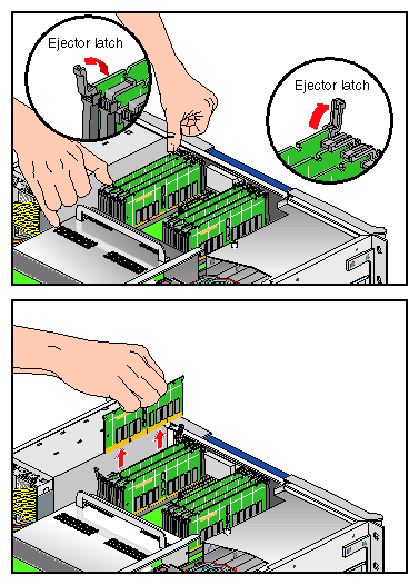
Note: If you need to find the correct location in which to install the DIMMs, make sure to read the introductory material in “Memory”. Open the ejector latches.
Hold the DIMM only by its edges and remove it from its antistatic package.
Align the three notches in the bottom edge of the DIMM with the keyed socket.
Insert the bottom edge of the DIMM into the socket, and then press down on the DIMM until it seats correctly. Use extreme care when you install a DIMM. If you apply too much pressure, you can damage the socket.
Gently push the plastic ejector latches down to secure the DIMM, as shown in Figure A-8. When the DIMM is fully seated in the connector, the ejector latches snap into place.
Repeat Step 5 for the second DIMM of the pair.
Replace the plastic air baffle.
Close the chassis by reversing the operation described in “Opening the Chassis”.
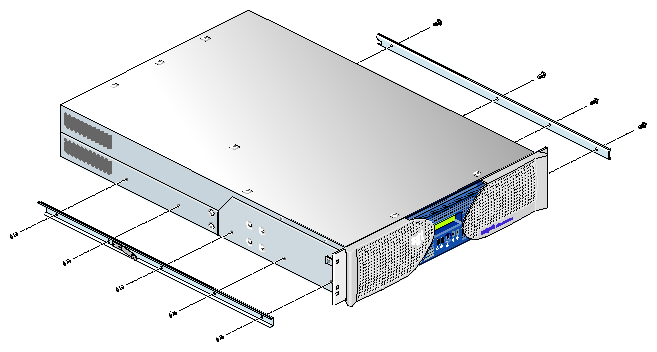
Press the safety latches on both sides of the brick and slide the brick into the rack.
Install the two screws that secure the brick to the front rails of the rack.
Install all of the cables at the rear of the brick.
Power on the host system as described in the user's guide that came with your host system.
To remove a DIMM, follow these steps:
Power off the host system as described in the user's guide that came with your host system.
Disconnect all of the cables at the rear of the brick.
Warning: Components may be hot. To avoid injury, allow the components to cool for approximately five minutes before you proceed with these instructions. Remove the two screws that secure the brick to the front rails of the rack.
Pull the brick from the rack until it is stopped by the safety latches.
Open the chassis as described in “Opening the Chassis”.
Remove the plastic air baffle covering the DIMMs, as shown in Figure A-9.
Remove the DIMM, as follows (see Figure A-10):
Note: If you need to find the correct location from which to remove the DIMMs, make sure to read the introductory material in “Memory”. Lift the two ejector latches simultaneously to disengage the DIMM from its connector.
Carefully grasp the DIMM and pull it up and out of the guide rails.
Note: Hold the DIMM only by its edges. Be careful not to touch its components or gold edge connectors. Place the DIMM on an ESD-safe surface.
If you are installing a new DIMM, proceed to “Installing a DIMM”. If you are not installing a new DIMM, proceed to the next step.
Repeat Step 7 for the second DIMM of the pair.
Replace the plastic air baffle covering the DIMMs.
Close the chassis by reversing the operation described in “Opening the Chassis”.
Press the safety latches on both sides of the brick and slide the brick into the rack.
Install the two screws that secure the brick to the front rails of the rack.
Install all of the cables at the rear of the brick.
Power on the host system as described in the user's guide that came with your host system.
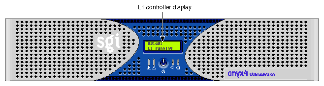
The L1 controller, which is used to monitor and manage the G2-brick or G2N-brick, has a display located on the front panel of the brick, as shown in Figure A-11. Every G2-brick and G2N-brick is factory-shipped with an L1 controller display. This section describes how to replace an L1 controller display panel.
To replace an L1 controller display, follow these steps:
Power off the host system as described in the user's guide that came with your host system.
Disconnect all of the cables at the rear of the brick.
Warning: Components may be hot. To avoid injury, allow the components to cool for approximately five minutes before you proceed with these instructions. Remove the two screws that secure the brick to the front rails of the rack.
Pull the brick from the rack until it is stopped by the safety latches.
Open the chassis as described in “Opening the Chassis”.
Remove the plastic air baffle covering the DIMMs, as shown in Figure A-7 in “Memory”.
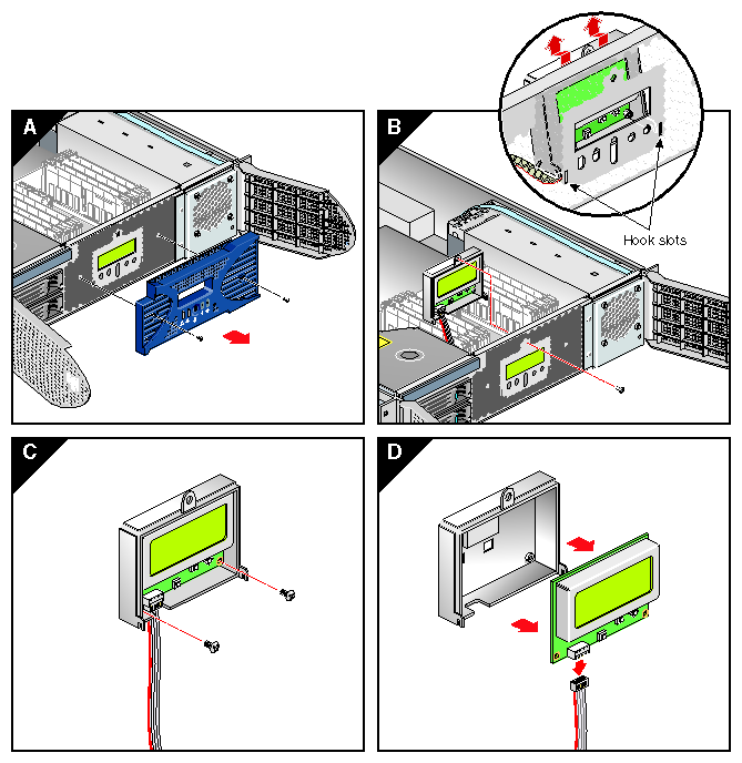
On the front panel of your system, remove the front bezel by unscrewing the two Phillips screws holding the bezel to the chassis, as shown in Figure A-12A.
Holding the L1 display cover with one hand, unscrew the single Phillips screw holding the L1 display cover to the chassis, as shown in Figure A-12B. Gently unhook and pull away the L1 display cover from the chassis.
Unscrew the two Phillips screws holding the L1 controller display panel to the L1 display protective cover, as shown in Figure A-12C.
Gently disconnect the L1 controller cable from the connector on the L1 controller display, as shown in Figure A-12D.
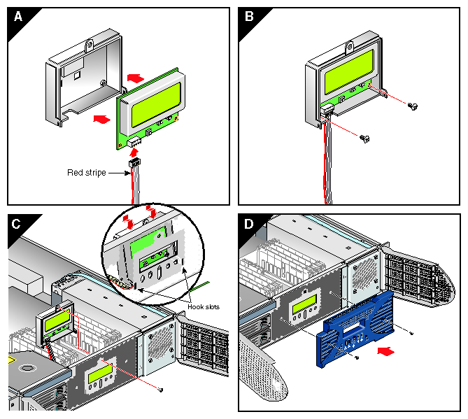
Connect the L1 controller cable to the connector on the new L1 controller display, making sure that the red stripe is to your left, as shown in Figure A-13A.
Align the two screw holes on the L1 controller display with the holes on the L1 display protective cover, and screw in the two Phillips screws, as shown in Figure A-13B.
Hook in the L1 display protective cover onto the slots on the front chassis and, holding the L1 display cover up against the front chassis, screw in the Phillips screw, as shown in Figure A-13C.
Replace the front bezel onto the front chassis of the system by screwing in the two Phillips screws holding the bezel to the chassis, as shown in Figure A-13D.
Replace the plastic air baffle covering the DIMMs.
Close the chassis by reversing the operation described in “Opening the Chassis”.
Press the safety latches on both sides of the brick, and slide the brick into the rack.
Install the two screws that secure the brick to the front rails of the rack.
Install all of the cables at the rear of the brick.
Power on the host system as described in the user's guide that came with your host system.
To replace a graphics card, follow these steps:
Power off the host system as described in the user's guide that came with your host system.
Disconnect all of the cables at the rear of the brick.
Warning: Components may be hot. To avoid injury, allow the components to cool for approximately five minutes before you proceed with these instructions. If the brick is rackmounted, remove the two screws that secure the brick to the front rails of the rack. If the brick is mounted with shelf rails, remove the screws at the rear also. If the brick is not rackmounted, proceed to step 6.
If the brick is mounted with the optional slide rail kit, pull the brick from the rack until it is stopped by the safety latches. Otherwise, two people should lift the unit from the rack and place it on a stable work surface.
Using two people, remove the brick from the optional slide rails by depressing the safety latches and sliding the brick outward. Place it on a stable work surface.
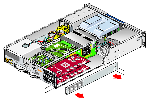
Remove the optional chassis rail by unscrewing the five Phillips screws (see Figure A-14).
Open the chassis as described in “Opening the Chassis”.
Make sure that you read “Safety Instructions ”, before beginning removal of a graphics card.
Remove the lower PCI/PCI–X support bracket by unscrewing the four Phillips screws, as shown in Figure A-15.
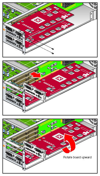
Undo and remove the two screws that hold the card to the back panel, as shown in Figure A-16.
Caution: Each graphics card is connected to the riser board by a 7-pin synchronization cable connected from the PCI riser board to the underside of the graphics card. Be careful not to pull the graphics card away from the board too far as you remove it. Pull the card gently out of the main connector on the riser board until it is clear of the back panel and main connector.
Carefully turn the graphics card over and disconnect the 7-pin keyed synchronization cable from the bottom (it attaches the graphics card assembly to the PCI riser board). See Figure A-17.
Place the graphics card on an ESD-safe surface or in a protective bag.
To install a new graphics card, use the following steps:
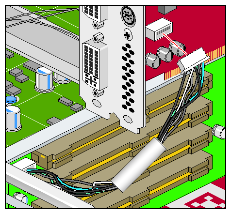
Place the card close to the graphics connector on the riser board and tilt it up until you can see the connector location for the 7-pin synchronization cable.
Gently insert the 7-pin synchronization cable into the connector on the bottom of the replacement graphics card, see Figure A-17. The connector is keyed and will only insert in the proper orientation. You should hear or feel a slight snap as the connector is seated.
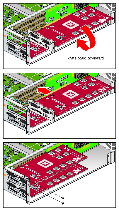
Insert the card into the slot from which the old graphics card was removed by pushing the card into the connector until it is properly seated and installing the back panel retaining screws, as shown in Figure A-18.
Be careful not to snag the 7-pin synchronization cable between the graphics card and the riser board connector when you install the new card.
Replace the lower PCI/PCI–X support bracket and screw in the four Phillips screws, as shown in Figure A-19.
Replace the optional chassis rail (if applicable) by screwing in the five Phillips screws (see Figure A-14).
Close the chassis by reversing the operation described in “Opening the Chassis”.
If your system uses optional slide rails, follow substeps a-d; otherwise go to step 8.
Fully extend the left and right slide rails from the rack until they lock into place.
This step requires two people. With one person holding each side of the brick, align the chassis rails of the brick with the slide rails of the rack.
Slide the chassis rails into the slide rails until the chassis rails are stopped by the safety latches.
Press the safety latches on both sides of the brick, and slide the brick into the rack.
For bricks mounted on shelf rails, use two people to slide the unit into the rack.
Install the two screws that secure the brick to the front rails of the rack. For shelf mounted units, secure the two screws at the back.
Install all of the cables at the rear of the brick.
Power on the Onyx4 system.
